How to Configure LAG/LACP and VLANs using SFP Ports on Two TP-Link Switches

Photo by blickpixel from Pexels
Table of Contents
In this guide, I will be demonstrating how to set up a LAG (Link Aggregation Group) using LACP. The two TP-Link switches used as examples are the TP-Link T1500G-10MPS Power over Ethernet (PoE) smart switch (affiliate link) and the TP-Link T2600G-28TS switch (affiliate link) .
The purpose of using a LAG between two network switch is to increase redundancy and performance. If one link fails, the other link will be utilized. Performance is also increased when you have multiple streams of data flowing between the two switches.
SFP Ports
Both of the TP-Link switches have SFP ports which can be used to connect to other SFP devices such as other network switches. The nice thing about using these ports is that you do not have to use up any of your Ethernet connections.
With SFP ports, you may use either fiber optic cables with SFP modules or SFP DAC (Direct Attached Copper) cables (affiliate link) which have the modules integrated onto a copper cable. Even though fiber optic cables are cheaper, purchasing several SFP modules along with the fiber cables can be more expensive than DAC cables.
The SFP ports on the TP-Link switches are not vendor locked so most any SFP modules and DAC cables should work.
Link Aggregation Group (LAG)
Multiple physical Ethernet/SFP ports can be grouped together as a single logical port. This is called a Link Aggregation Group (LAG). LAGs are beneficial for increasing bandwidth and reliability between connected devices. The TP-link T1500G-10MPS has two SFP ports and the TP-Link T2600G-28TS has 4 SFP ports.
Link aggregation can be set up using a static LAG configuration or using LACP (Link Aggregation Control Protocol).
Configuring Link Aggregation using LACP
I will step through configuring the T2600G-28TS switch first and then the T1500G-10MPS. Keep in mind that my T2600G-28TS is a version 2 model so the web interface is not the same as the newer TP-Link switch models such as the T1500G-10MPS.
Warning
You must configure the link aggregation on both switches before plugging in the cabling! The reason for this is that when two or more cables are plugged between two switches, you will create a broadcast storm (a network loop) that may take down your network. Please keep that in mind while you are configuring your switches.
Configuring LACP on the TP-Link T2600G-28TS
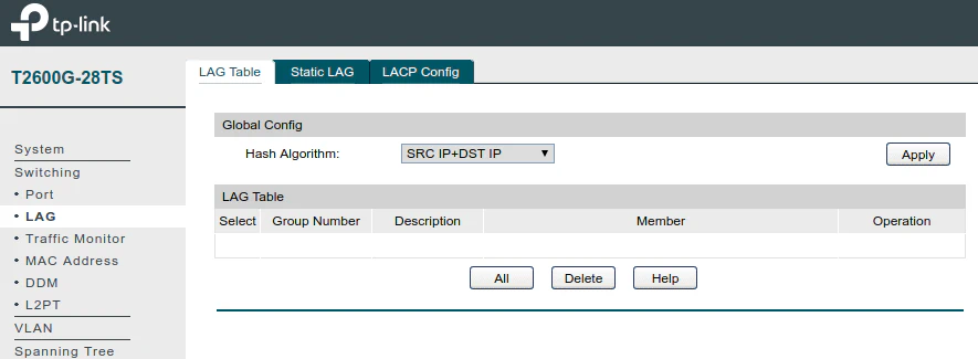
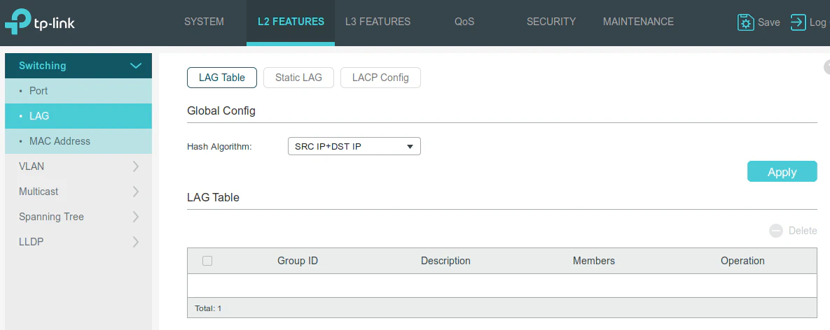
Go to the “Switching > LAG” page as shown below. There should not currently be any LAGs displayed in the “LAG Table” section.
You may change your “Hash Algorithm” if you desire. In the example below, I used the SRC IP+DST IP algorithm (be sure to click the “Apply” button). Ultimately it probably does not make a huge difference which algorithm you choose on a home network with a relatively low volume of traffic.
However, it may be better to choose an algorithm that includes both the source and destination in the hash since it may help distribute the network traffic more evenly across the LAG ports. I will show a screenshot later which helps demonstrate and validate that assertion.
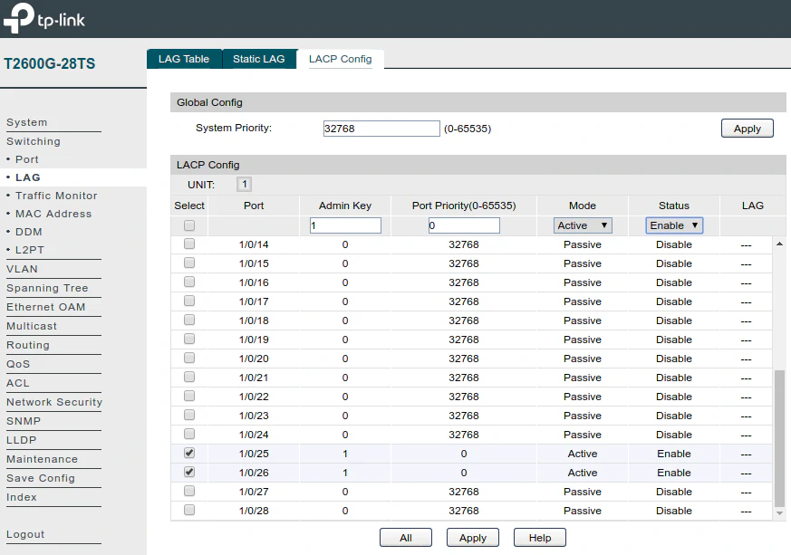
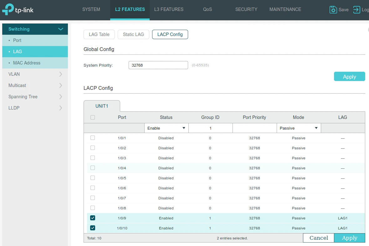
Next click the “LACP Config” tab to set up the new LAG. You may select both of your SFP ports at the same time to apply the same settings across both ports.
I chose the “Admin Key” of 1, “Port Priority” of 0, “Mode” set to Active, and “Status” set to Enabled to enable LACP on the ports. Click the “Apply” button.
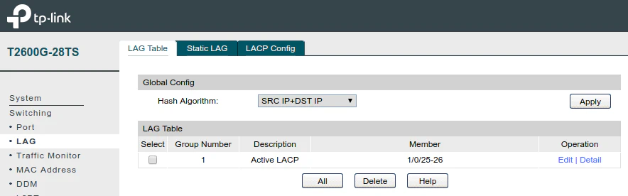
After clicking “Apply” you should now see the LAG on the “LAG Table” tab.
Configuring LACP on the TP-Link T1500G-10MPS
Configuring the LAG on the TP-Link T1500G-10MPS is similar to the TP-Link T2600G-28TS. The location of the items on the interface is the main difference.
Go to the “L2 Features” tab, then click “LAG” from the left menu. There should be nothing in the “LAG Table” section.
You may set the “Hash Algorithm” on this page as well to SRC IP+DST IP. I do not know if it needs to be the same as the other switch, but it may be a good idea to make it the same to be consistent. Click the “Apply” button.
Now go to the “LACP Config” section and configure it the same way as before. Set the “Status” to Enable and “Group ID” to 1. The main difference you will notice is that I set the “Mode” to Passive mode on this switch.
Click “Apply” at the bottom of the “LACP Config” table.
Note
When researching online, I saw mention that many switches do not include Passive mode so it would ok to have both switches set to Active mode. However, when I tried that, I had issues with connectivity to the T1500G-10MPS switch for some reason.
It was possible I had some other misconfiguration, but things have been working great with the “Active-Passive” configuration. TP-Link’s own documentation shows a similar configuration so perhaps their switches work better that way. I made my main T2600G-28TS switch the active since if it goes down most if my network will be down anyway.
The “LAG Table” should show your newly created LAG.

Configuring VLANs on the Newly Created LAG
If you are using VLANs, it is time to configure new VLANs and/or update existing VLANs. Configuring VLANs on a LAG is similar to configuring VLANs on the individual Ethernet ports. The LAG is treated as a single logical interface even though it consists of two or more physical ports.
The first thing you should do is change the LAG to be a TRUNK “Link Type” instead of ACCESS on both switches. This allows VLAN traffic to flow through the port properly.
You can think of needing the TRUNK “Link Type” when VLAN traffic traverses between network infrastructure such as network switches and routers.
The ACCESS “Link Type” is used for client devices connected to your network such as computers, printers, etc. The network switch will tag the traffic that flows out of the ports with “Link Type” of ACCESS and it will remove the VLAN tag for traffic flowing into those ports. The devices on those ports are not aware that they live on a VLAN since the switch handles tagging and untagging that traffic.
Note
One thing to note with the older TP-Link firmware: you have to set the “Link Type” to TRUNK before creating new VLANs. Otherwise, you will not have any ports select as the trunk/tagged ports when configuring VLANs.
With the newer firmware, I have noticed that you can select any port you want to be a trunk/tagged port at the same time you create a new VLAN.
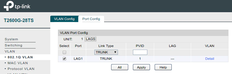
To set the “Link Type” of a port to TRUNK with the older firmware on the T2600G-28TS switch, go to the “VLAN” menu, then “802.1Q VLAN”, and click on the “Port Config” tab.
Since we are wanting to allow VLAN network traffic between the two switches, you will need to select the “LAGS” section beside the “UNIT:” heading. You should see the LAG that you just configured earlier. Check the box beside the LAG and choose TRUNK from the dropdown menu. Click “Apply” to save the changes.
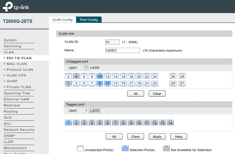
Now you can set up your VLANs in the “VLAN Config” tab. In the example in the screenshot, I have created a VIDEO VLAN and selected 3 untagged ports (ports 9-11). These are the ports that will be used by the NVR (the NVR does not provide power via PoE to the cameras) and other devices which will be used as IP camera monitors.
In the tagged ports section, click on “LAGS” and then click the LAG you have configured. This will allow the VIDEO VLAN network traffic to flow to our other switch. Click “Apply” to save your changes.
Next you will need to repeat this process on the second switch. Since it has the newer TP-Link firmware, you simply go to “L2 Features” and then click the “VLAN” menu.
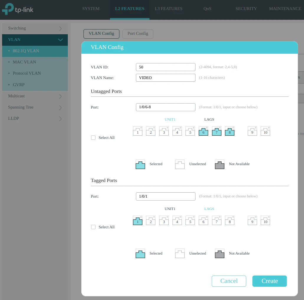
Add a new VLAN via the “VLAN Config” section. Select the ports used by your devices as the “Untagged Ports”. Ports 6-8 will be the untagged ports used for PoE powered IP cameras.
Click “LAGS” in the “Tagged Ports” section to select the LAG you created so that traffic can flow between the switches.
When you are finished, click on the “Create” button to create the VIDEO VLAN.
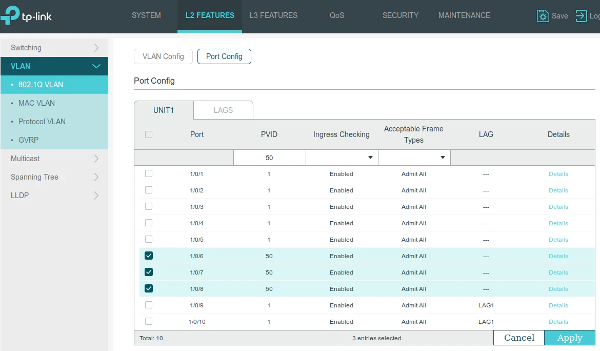
One more thing that needs to be done with the newer firmware that is not necessary with the older firmware. The older firmware automatically set the PVID of the untagged ports once you added the ports to a VLAN.
For the newer firmware, I you have to go to the “Port Config” section and set the PVID of the ports to the VLAN IDs you have set up. In the example below, I set ports 6-8 to PVID of 50 for VLAN 50. Click the “Apply” button to save the changes.
If you have several VLANs, you will need to repeat the above process for each VLAN on both switches.
Connect Both Ports of the LAG
At this point you will want to connect both ports of the LAG on both switches (ports 25 and 26 of the T2600G-28TS to ports 9 and 10 of the T1500G-10MPS). If your network becomes unresponsive, you will know something is not configured properly.
If everything seems to be working without issue, be sure to save the configuration of both of the TP-Link switches so that the changes are not lost when rebooting. For the T2600G-28TS, click the “Save Config” menu option on the left side of the page. For the T1500G-10MPS, click the “Save” in the upper right hand corner of the page.
You should now have a higher bandwidth link with failover established between the two TP-Link switches and as well as have VLAN traffic flowing between them!
Optionally Verify LAG Network Traffic
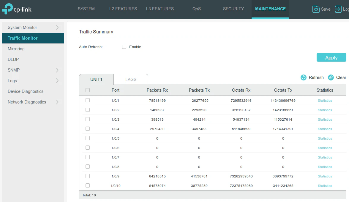
If you like to take a peek at how your network traffic is being distributed between the two ports in your LAG, you can go to the switch’s network monitor page. This will give you a good idea whether or not your network traffic is being evenly distributed or if it is only using one of the two ports.
For the older TP-Link firmware, go to the “Switching” menu and then “Traffic Monitor”. You can see that the traffic is relatively evenly distributed between the two LAG ports (ports 25 and 26).
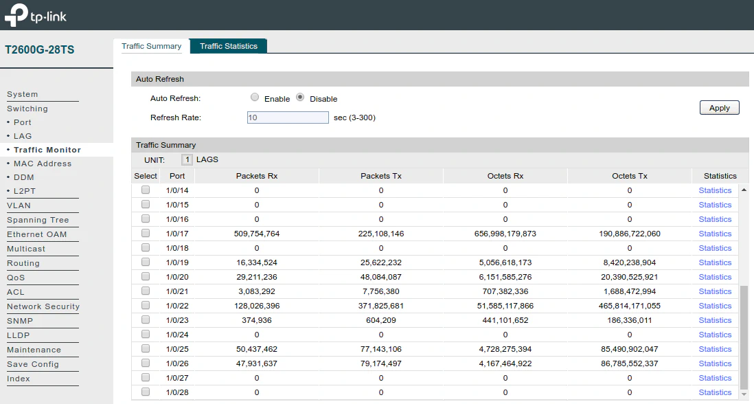
For the newer firmware, go to “Maintenance” and then “Traffic Monitor”. You can see the traffic on the LAG ports (ports 9 and 10) are pretty even.