How to Set Up a Transparent Filtering Bridge on OPNsense 24.7

Photo by alexsl from Getty Images
Table of Contents
Many users have ISP supplied routers or their own gateway/router devices that they must use or prefer to use yet want to add greater security to their networks without replacing their current gateway/router. A transparent filtering bridge allows users to deploy a firewall in their networks while utilizing existing network infrastructure.
This guide will demonstrate how to set up a transparent filtering bridge in OPNsense 24.7 as well as how to set up a few security protections after the bridge has been configured.
If you are using OPNsense 25.7 or newer, please refer to my updated transparent filtering bridge guide since it includes the configuration for dnsmasq DHCP which is the default DHCP service in 25.7 and newer versions of OPNsense.
What is a Transparent Filtering Bridge
A transparent filtering bridge is able to inspect network traffic traversing on one physical network interface and forward the traffic to another network interface if it is allowed to pass depending on the firewall rules and other security protections that are in place.
Two physical network interfaces is the minimum number of interfaces you will want to use for a transparent filtering bridge: one for the incoming connection and one for the outgoing connection.
Location of a Transparent Filtering Bridge
There are a number of locations where you might put a transparent filtering bridge on your network depending on where you wish to have additional security protections.
Between the modem and router
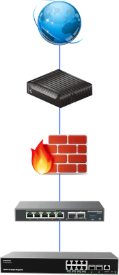
If you have a separate modem/ONT and a separate router, you may put the transparent filtering bridge between your modem and router so the firewall is located at the outermost part of your network.
Some users may want this option if only interested in protecting the perimeter of their networks.
There are a couple of things to note:
-
The source or destination IP address will be the public WAN address of the router so you will not know which device within your network where the traffic is originating from. Therefore you lose some visibility of traffic in your network.
-
While you are able to block traffic entering/leaving your network, you will not be able to block any traffic within your network (between various VLANs, etc.) since the bridge is located before the router’s WAN interface.
Between the router and network switch
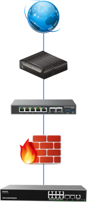
If you have an all-in-one modem/ONT/router or a router/gateway appliance you prefer using instead of OPNsense, you may put the transparent filtering bridge between the router and network switch.
This assumes you are using a router-on-a-stick configuration where everything on the network is connected to the network switch which is connected to the router. If you connect devices to other network interfaces on the router when you have the transparent bridge between the router and switch, the traffic from the devices connected to the router will not be filtered by the bridge.
The great advantage of locating the transparent bridge between the router and network switch is that you can filter traffic within your local network in addition to traffic entering/leaving your network via the WAN interface. You will have greater visibility of your internal network (on various VLANs, etc.) since all of your local routed network traffic must traverse through the router and therefore the transparent bridge.
The example in this guide will use this location for the transparent bridge.
On a single VLAN such as the DMZ network
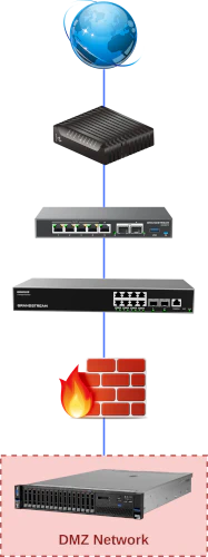
Another possible location you may wish to consider is placing a transparent filtering bridge on a particular VLAN such as a DMZ network.
Even if your primary network router has robust firewall and other security features, you may wish to deploy a second firewall to better protect your local network from the public facing DMZ network.
Businesses may wish to choose to use a different vendor for the secondary firewall to minimize the likelihood that an exploit on one brand of firewall would be exploited on the secondary firewall if it was same vendor.
For home networks, using firewalls of two separate vendors is probably unnecessary from a security standpoint, but you may wish to do so if you enjoy learning how to use different firewall products.
Essentially, you can place a transparent bridge between any two devices on your network. I even tested the transparent filtering bridge between two PCs so that I could test throughput of the Gown R86S-P2 used in my example network. In case you are curious how much CPU you need (for up to 2.5 Gbps networking), I could get 1.8-2 Gbps with Zenarmor enabled with an Intel N5105 CPU, which is pretty good for an older, slower CPU. The R86S-P2 can almost fully saturate 2.5 Gbps.
Example Network
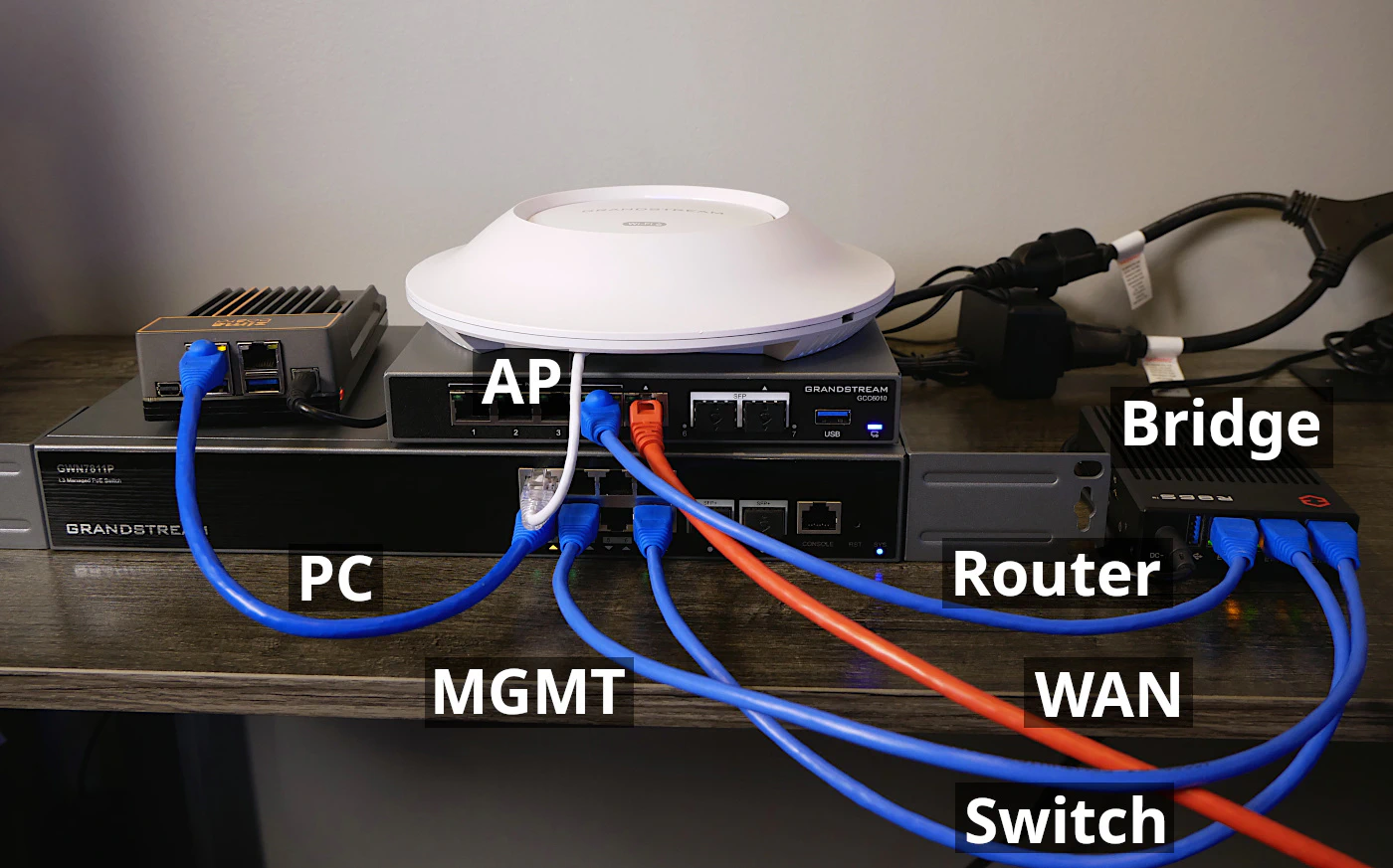
Below is an image of an example network that I will be using in this example. It consists of an existing router (the Grandstream GCC6010), network switch (Grandstream GWN7811P), and wireless access point (Grandstream GWN7664E). There is also a PC on the network (the ZimaBoard 832).
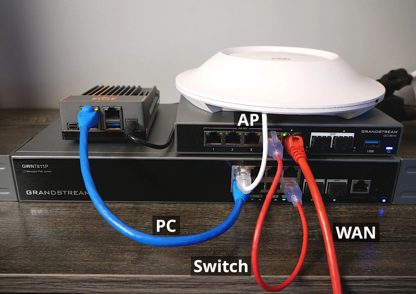
In the example scenario for this guide, I am going to be placing the transparent bridge device (Gowin R86S-P2) between the router and network switch because of the increased visibility of the devices on the network as mentioned earlier.
Warning
Do not plug the OPNsense system into your existing network until you are finished configuring the transparent bridge.
A couple of reasons for not connecting the OPNsense system to the existing network:
-
The default LAN interface has DHCP running and would interfere with the DHCP service running on your existing network.
-
The two transparent bridge interfaces are not yet configured and would take down whatever part of your network where you want the transparent bridge to exist (potentially taking down your entire network).
What is Different about this Guide?
Most transparent filtering bridge guides will demonstrate how to set up a filtering bridge with only two network interfaces. However, I am going to demonstrate using three physical interfaces. I am a big fan of having a dedicated management interface for all my network infrastructure such as the router/firewall, server(s), NAS, and other devices.
One advantage of having a third interface dedicated for management is that you cannot get locked out of the OPNsense web interface while you are configuring the bridge interface. A common problem I often notice is users inadvertently locking themselves out of the web interface – even if the bridge itself may be functioning properly.
1. Install OPNsense
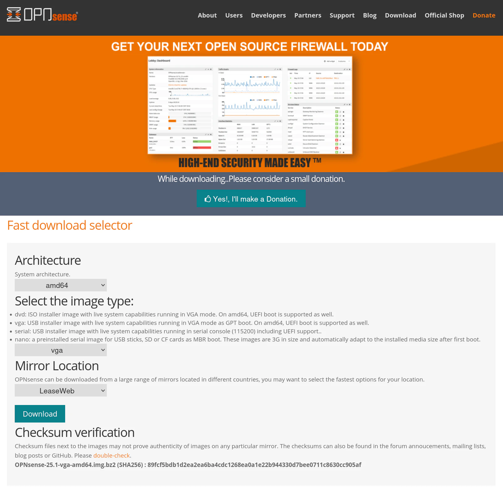
For the OPNsense installation, you will need to go to the download page of OPNsense and select the VGA image if you wish to image a USB drive for installation OPNsense. You may use software such as Etcher to copy the image to the USB drive.
For this guide, simply let the installer boot without pressing any keys so it uses the default settings for the WAN/LAN interface assignments. Depending on your device will depend on the order of the interfaces. In most cases, OPNsense will default to using the first interface for LAN and the 2nd interface to WAN.
Once you arrive at the login prompt, enter installer as the username and opnsense as the password to install OPNsense.
Then simply follow the normal OPNsense installation process. I will not describe the full process in this guide since I have another guide discussing a basic installation.
After the installation is complete, plug your PC into the LAN port and log into the OPNsense web UI at https://192.168.1.1.
2. (Optional) Change Default IP Addresses of LAN Interface
Many home users are using the default network IP address of 192.168.1.1/24 (which is 192.168.1.1-192.168.1.254). In an effort to make this guide more comprehensive and to demonstrate a likely common scenario, I will make the assumption that the existing network is using that IP range. If you are not using this range of IP addresses, you may skip this step!
Why is it important to note this assumption? OPNsense also uses the same network range for the default LAN interface. Therefore I recommend changing the default IP address range for the LAN interface in OPNsense before configuring the new MGMT interface since the goal is to put the MGMT interface on the existing 192.168.1.1/24 network.
Not only that, if you create a new MGMT interface with a static IP in the 192.168.1.1/24 range, it would conflict with the default LAN interface of OPNsense. By doing this step, you will be able to verify the new MGMT interface is working properly before you add the original, default LAN interface to the filtering bridge. A good rule of thumb is to always verify that you have access to new management interface before you get rid of or change the configuration of the old management interface.
2.1 Change LAN Interface IP
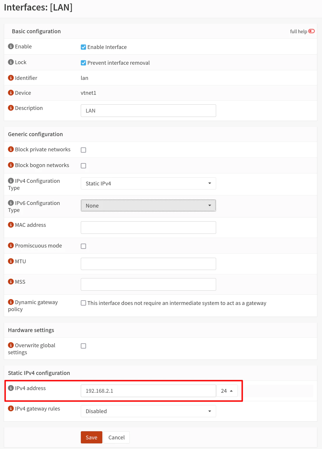
On the “Interfaces > [LAN]” page, go to the “Static IPv4 configuration” section at the bottom of the page. Change the “IPv4 address” to 192.168.2.1 (keep the CIDR range at /24).
Click the “Save” button but do not click “Apply changes” yet! If you click “Apply changes”, you will get disconnected from the web UI before you can change the DHCP range (not a huge detail technically since you could set a static IP on your PC to get back in).
2.2 Change the LAN’s DHCP IP Address Range
Now that the interface IP has been changed (but not yet applied), you will be able to updated the DHCP IP address range for the LAN interface.
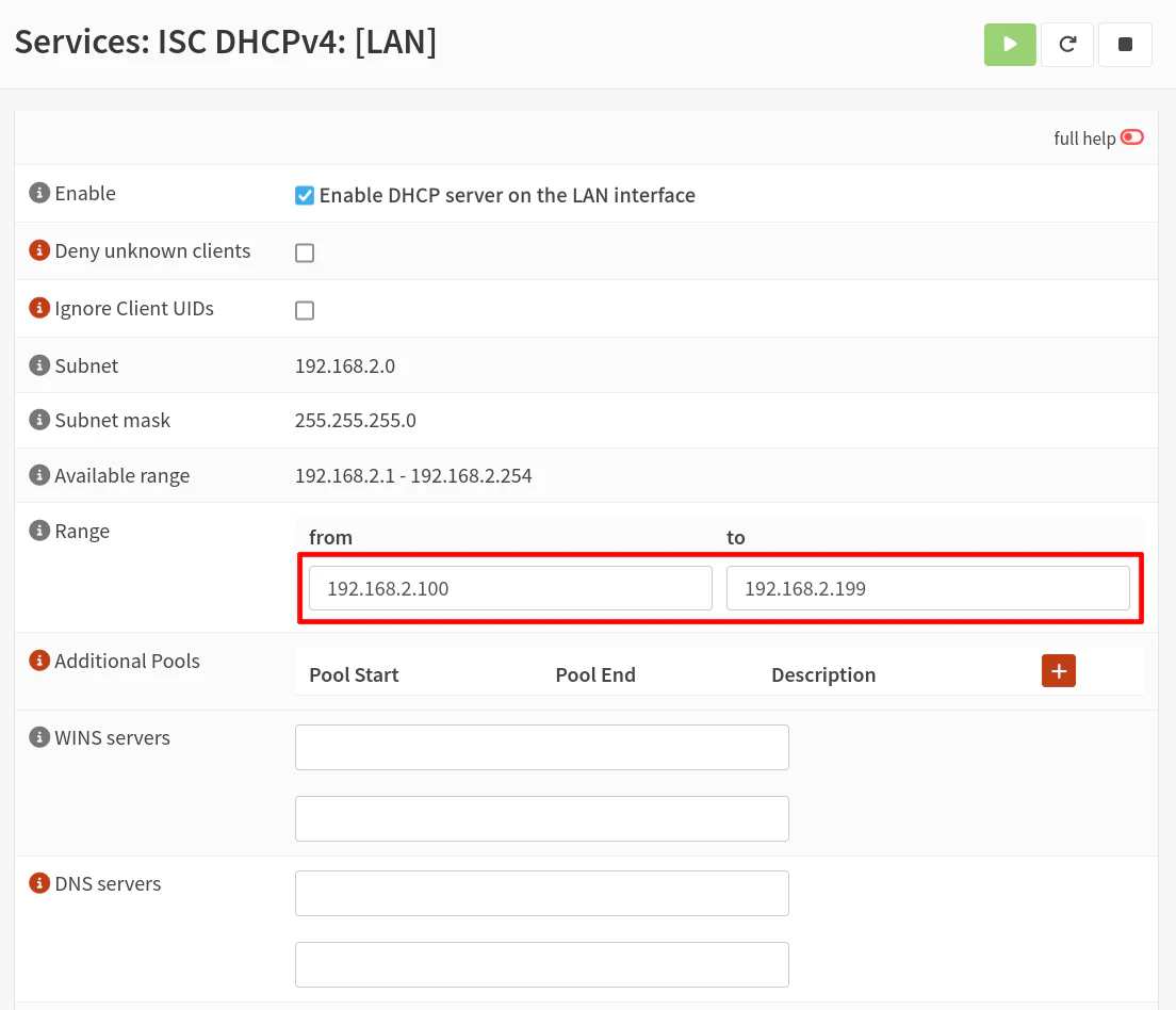
Go to the “Services > ISC DHCPv4 > [LAN]” page. For the “Range” section change the “from” to be 192.168.2.100 and the “to” to be 192.168.2.199. Click “Save”.
2.3 Apply LAN Interface Changes
You may now go back to the “Interfaces > [LAN]” page and click “Apply changes”. You will temporarily lose access to the OPNsense web UI. If you disconnect and reconnect your PC (or initiate a DHCP release and renew), you should have an IP address in the 192.168.2.x network.
Log back into OPNsense by visiting https://192.168.2.1.
3. Configure a New Management Interface
You might be thinking: ‘Could we not simply use the default LAN interface as the management interface but create the bridge on two other physical interfaces?’
Yes, you could do that, but you risk locking yourself out of the OPNsense web UI if you do not change the settings properly. Of course, you should be able to fix any mistakes you made by logging directly into the console of OPNsense via keyboard/mouse.
If you wish to go down that route, you may do so if you feel comfortable making those changes. However, this guide will walk you through a safe approach of ensuring the new interface works before removing or changing existing interfaces.
3.1 Assign the MGMT Interface
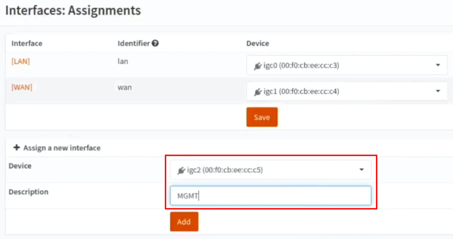
First step in creating a MGMT interface is to go to the “Interfaces > Assignments” page.
There should be unused network interfaces listed in the “Device” dropdown such as igc2 in my example. Select an unused network interface you wish to use as the MGMT interface.
Add a “Description” to the interface such as MGMT so that the interface does not show up as OPT1 in the sidebar, for example.
Click the “Add” button to assign the interface.
3.2 Enable the MGMT Interface
On the left side menu, you should see a new menu option called “[MGMT]”. Click on that option to go to the MGMT interface page.
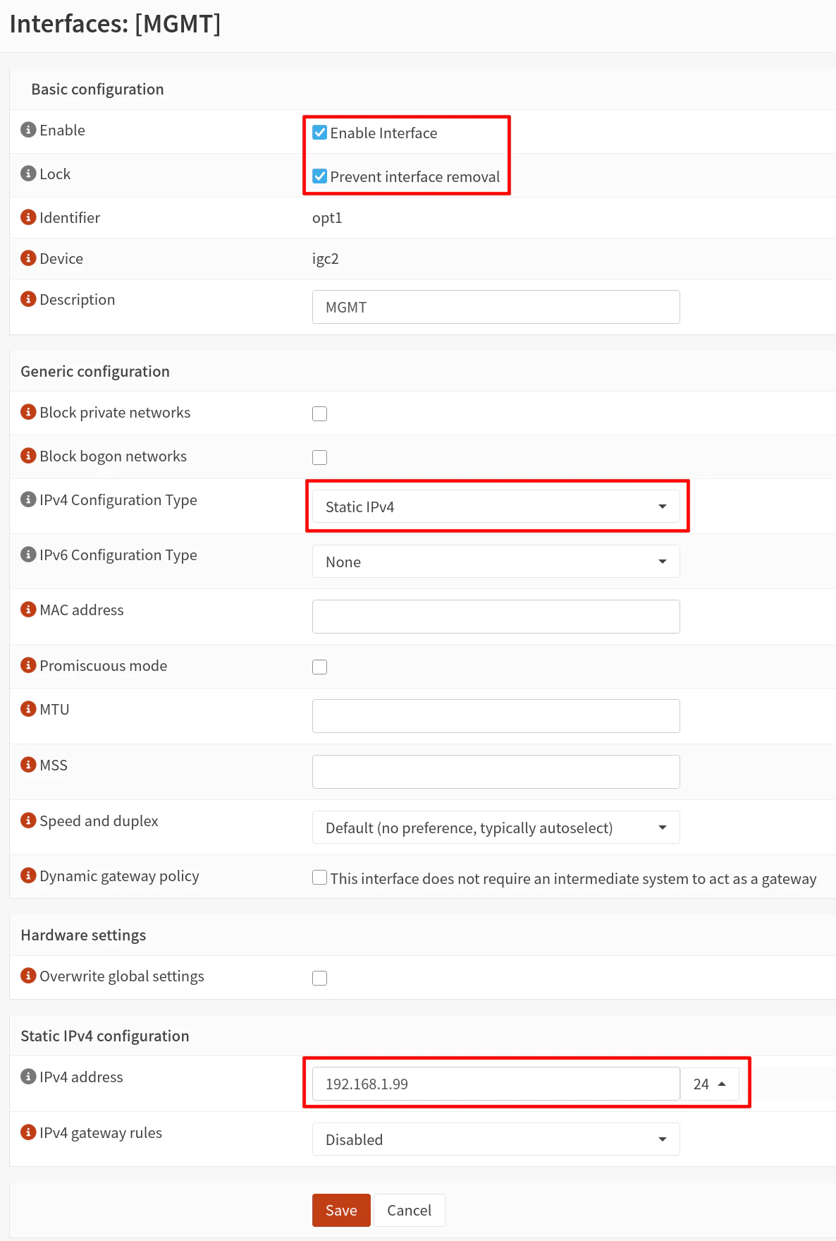
Click the “Enable Interface” checkbox so that additional options for the interface are displayed on the page. I recommend checking the “Prevent interface removal” option as a safety to reduce the likelihood of accidentally removing the interface if you need to make changes later.
For the “IPv4 Configuration Type”, select the Static IPv4 option to set a static IP for the management interface. You need to set an IP address that falls in the same subnet as the network where you plan to management the OPNsense transparent filtering bridge.
Generally speaking, it is a best practice to set a static IP address for critical network infrastructure and management interfaces since you can still access the page even if the DHCP service is down on your network for an extended period of time (which would allow the DHCP leases to expire and your device would no longer have an IP addressed assigned via DHCP).
In the “Static IPv4 configuration” section, enter an “IPv4 address” such as 192.168.1.99/24. Note that you need to use /24 in the CIDR dropdown box (assuming your management network is also a /24 sized network). You will need to ensure the static IP address is not located in the DHCP range you have set on your primary router and does not conflict with any other static IP addresses on your management network.
Click “Save” at the bottom of the page and then “Apply changes” at the top of the page.
3.3 Create the Appropriate Firewall Rule(s)
By default, new interfaces do not have any firewall rules assigned which means that all network traffic is blocked on the interface (due to the firewall’s “default deny” policy).
On the “Firewall > Rules > MGMT” page, you will want to add the following rule:
| Action | TCP/IP Version | Protocol | Source | Destination | Dest Port | Description | |
|---|---|---|---|---|---|---|---|
| Pass | IPv4 | TCP | MGMT net | MGMT address | 443 (HTTPS) | Allow access to OPNsense web UI |
Tip
If you wish to allow SSH access to the OPNsense system, you would also need to create a similar rule to the one above but use port 22 (SSH) instead of 443 (HTTPS).
Click “Save” and then “Apply changes”.
4. Test the MGMT Interface
Before you configure the bridge and remove the existing LAN interface (since it will become a part of the filtering bridge), you should test your access to the MGMT interface. This is the safest approach to ensure you do not lose access to your OPNsense system when setting up the filtering bridge.
4.1 Connect the MGMT Interface and PC to the Existing Network
At this point, you may connect the MGMT interface and the PC you are using the configure OPNsense to your existing network. I am assuming in this guide that the existing network is 192.168.1.x.
Because DHCP is not enabled on the new MGMT interface, you will need to configure a static IP address on your PC if you are directly connected to the MGMT interface such as 192.168.1.10 (must be a different IP than the MGMT interface IP).
Note
If the MGMT interface is plugged into your existing network, then you do not need to configure a static IP address for the PC since it should have an IP address assigned by the existing router on the network. As mentioned earlier, the MGMT interface must be configured to be on the same subnet as the network where you plan to manage the OPNsense transparent bridge.
4.2 Access the OPNsense Web UI via the MGMT Interface
Now you may enter https://192.168.1.99 to verify you can access and log into the OPNsense web UI.
Once you verified the new MGMT interface is working properly, you will be free to modify the configuration of the other two interfaces without worrying about losing access to OPNsense. Even if you do not correctly configure the transparent bridge, you will still have access to OPNsense as long as you do not modify the configuration of the MGMT interface.
5. Configure the Transparent Filtering Bridge
The steps in this section follow relatively closely to the OPNsense instructions with a few minor differences. Since a separate, physical MGMT interface has already been configured, you will be able to skip the OPNsense instructions on configuring a management interface on the filtering bridge interface.
5.1 Disable Outbound NAT Generation
Because OPNsense is going to operate as a filtering bridge rather than as a router, you can disable outbound NAT.
On the “Firewall > NAT > Outbound” page, click the radio button for “Disable outbound NAT rule generation”.
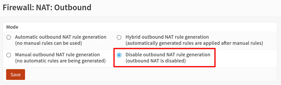
Click “Save” and “Apply changes”.
5.2 Modify the System Tunable Options
Next navigate to the “System > Settings > Tunables” page since a couple of system tunables need to be modified.
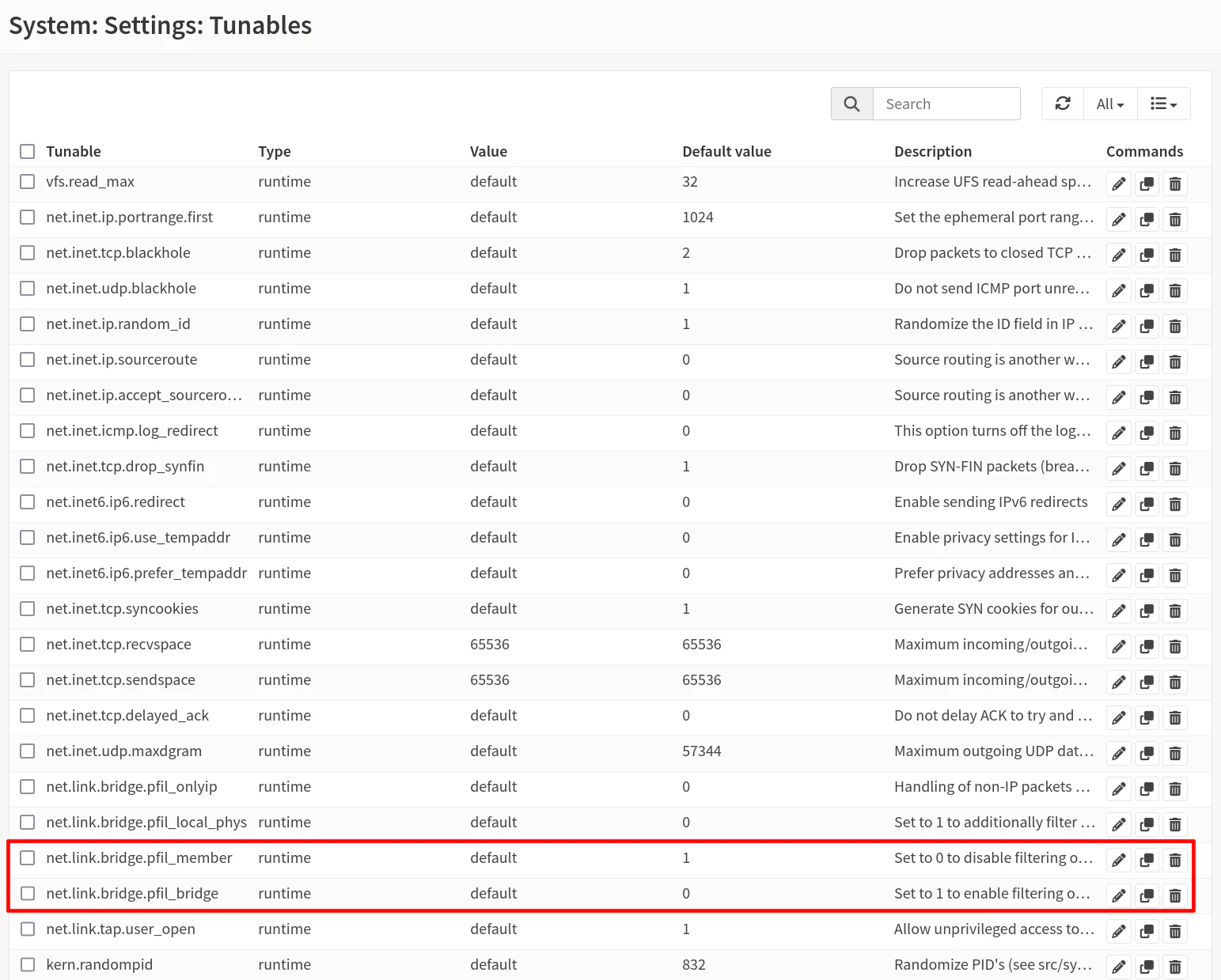
Press “Ctrl + F” in your browser to search for the text net.link.bridge.pfil_bridge or scroll down to find the tunable option. Click on the pencil icon to edit the entry. Enter 1 for the value to enable filtering on bridge interfaces.
When you return to the tunable page, search for the next tunable net.link.bridge.pfil_member, click on the pencil icon, and enter 0 for the value. This will disable filtering on the individual physical interfaces.
Click “Apply changes”.
5.3 Create the Bridge Interface
Visit the “Interfaces > Other Types > Bridge” page (or “Interfaces > Devices > Bridge” on OPNsense 25.1 and later). Click on the “+” button to add a bridge interface.
For the “Member interfaces”, you will need to select LAN and WAN. You can be creative with the “Description” or simply call it BRIDGE.
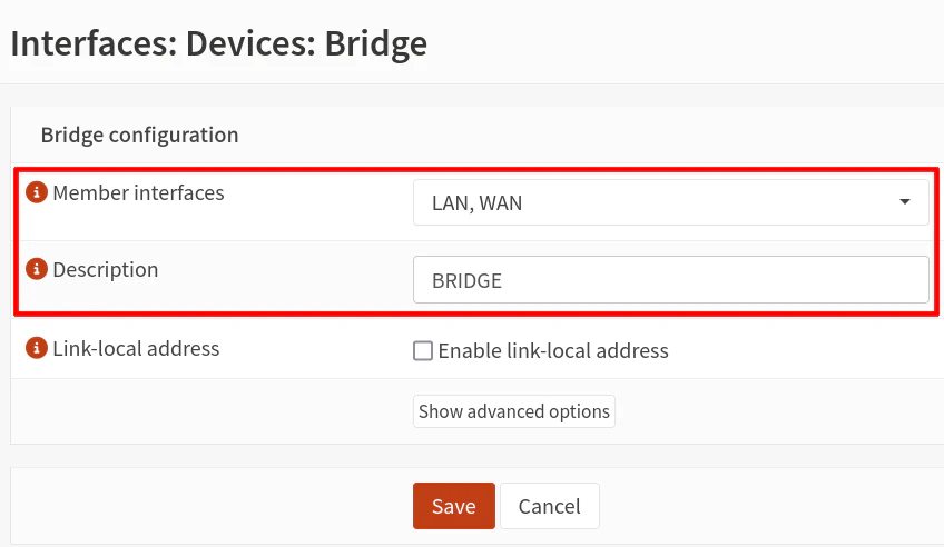
Click “Save”.
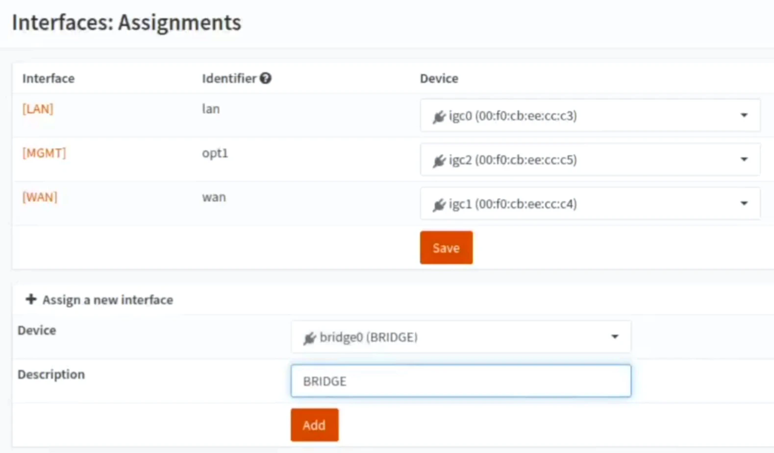
5.4 Assign the Bridge Interface
On the “Interfaces > Assignments” page, select the bridge for the “Device” from the dropdown. The value will be called bridge0 (BRIDGE).
Enter a “Description” for the interface such as BRIDGE. This will be the value that shows up on the left side menu and other places for the interface name so I recommend entering a useful, short name.
Click the “Add” button.
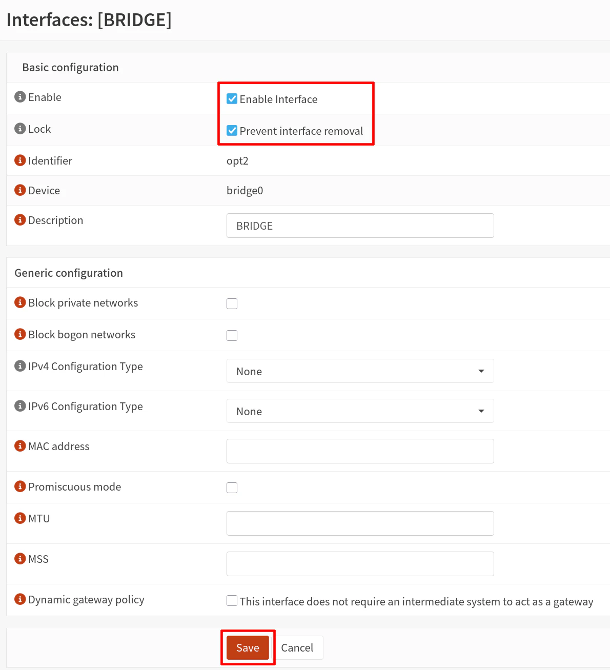
5.5 Enable the Bridge Interface
Now the bridge interface can be enabled by going to the “Interfaces > [BRIDGE]” page. Click the checkbox for “Enable Interface” as well as “Prevent interface removal”.
Leave everything at the default values.
Click “Save” and “Apply changes”.
5.6 Disable the Block Private Networks and Bogons on WAN Interface
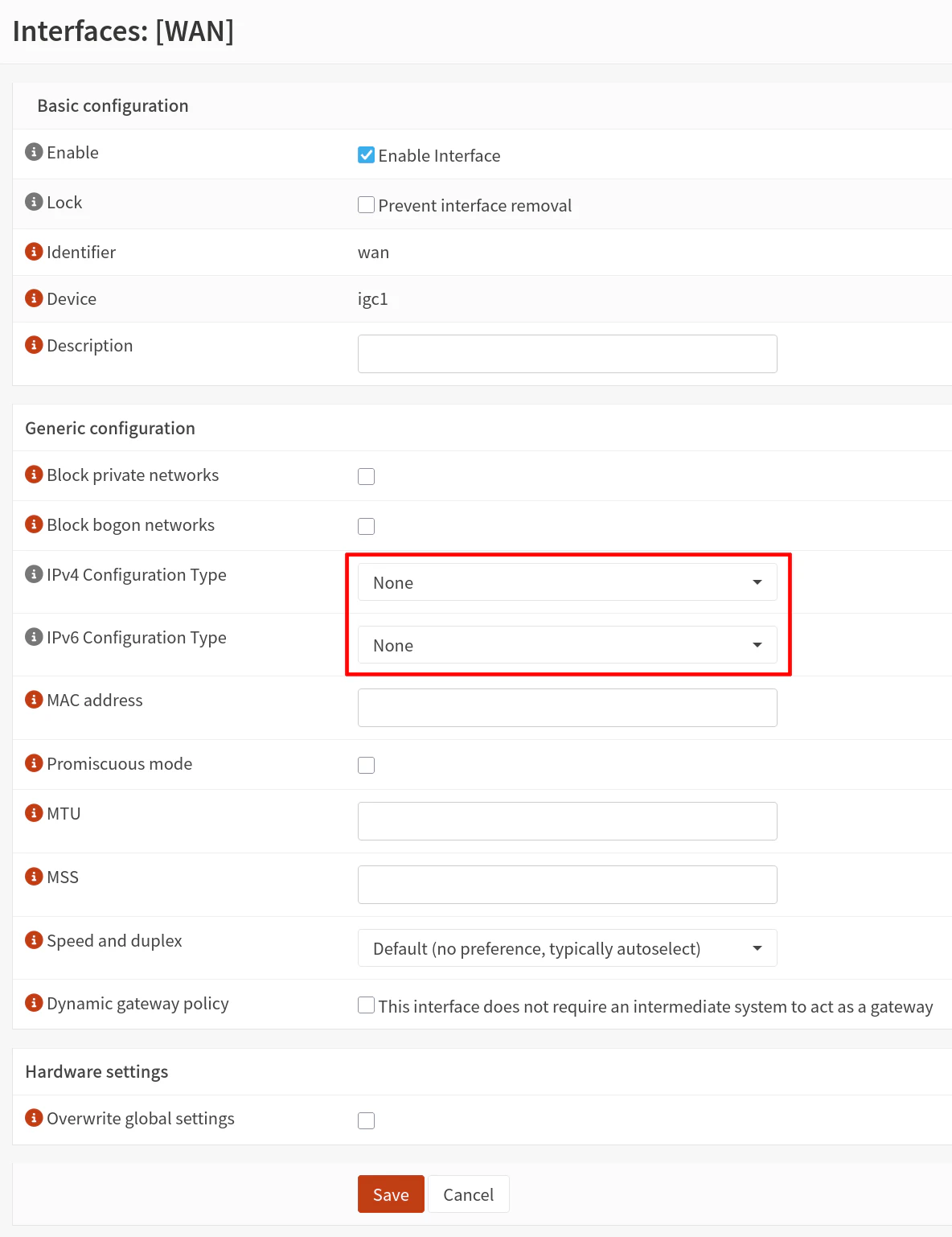
You will need to go to the WAN interface configuration page (“Interfaces > [WAN]”).
Uncheck the “Block private networks” and “Block bogon networks” options to prevent blocking internal, private IP addresses (since the bridge will be filtering traffic on your internal network(s)).
Please complete the next step (5.7) before clicking “Save” so you do not have to do it twice since there are more settings to change.
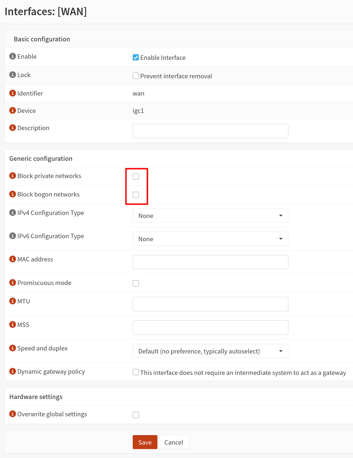
5.7 Disable IP Addresses on WAN Interface
While still on the WAN interface configuration page, you should also set the “IPv4 Configuration Type” and “IPv6 Configuration Type” options to None.
The physical interfaces of the filtering bridge do not need to have any IP addresses assigned to them because traffic will simply pass through the filtering bridge.
Click “Save”.
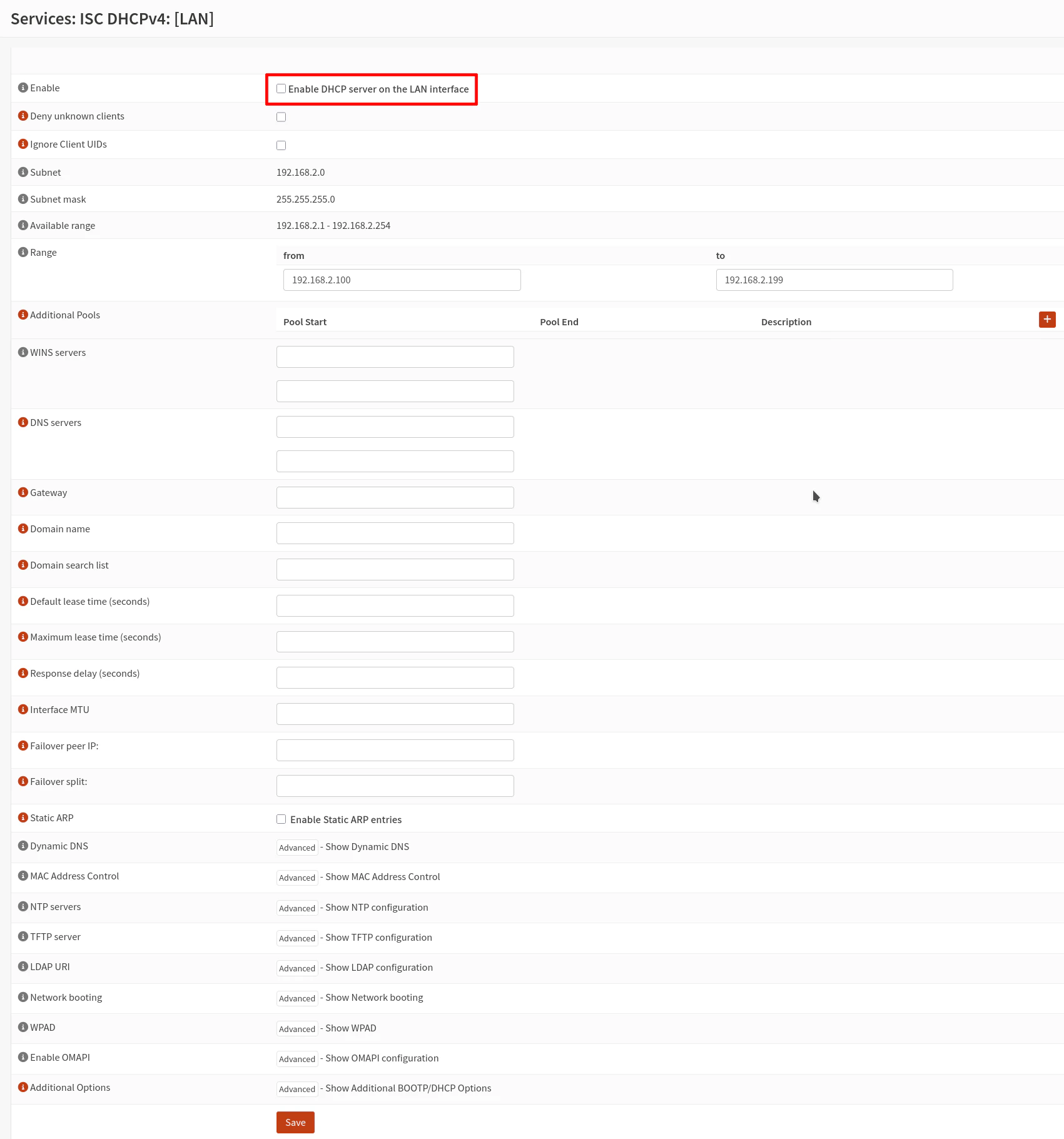
5.8 Disable DHCP Server on the LAN Interface
The DHCP service is no longer necessary on the original LAN interface so it can be disabled.
On the “Services > ISC DHCPv4 > [LAN]” page, uncheck the “Enable DHCP server on the LAN interface” checkbox.
Click “Save”.
The next couple of steps in the official OPNsense guide will be skipped since I am using a dedicated management interface that is separate from the transparent bridge unlike the OPNsense documentation.
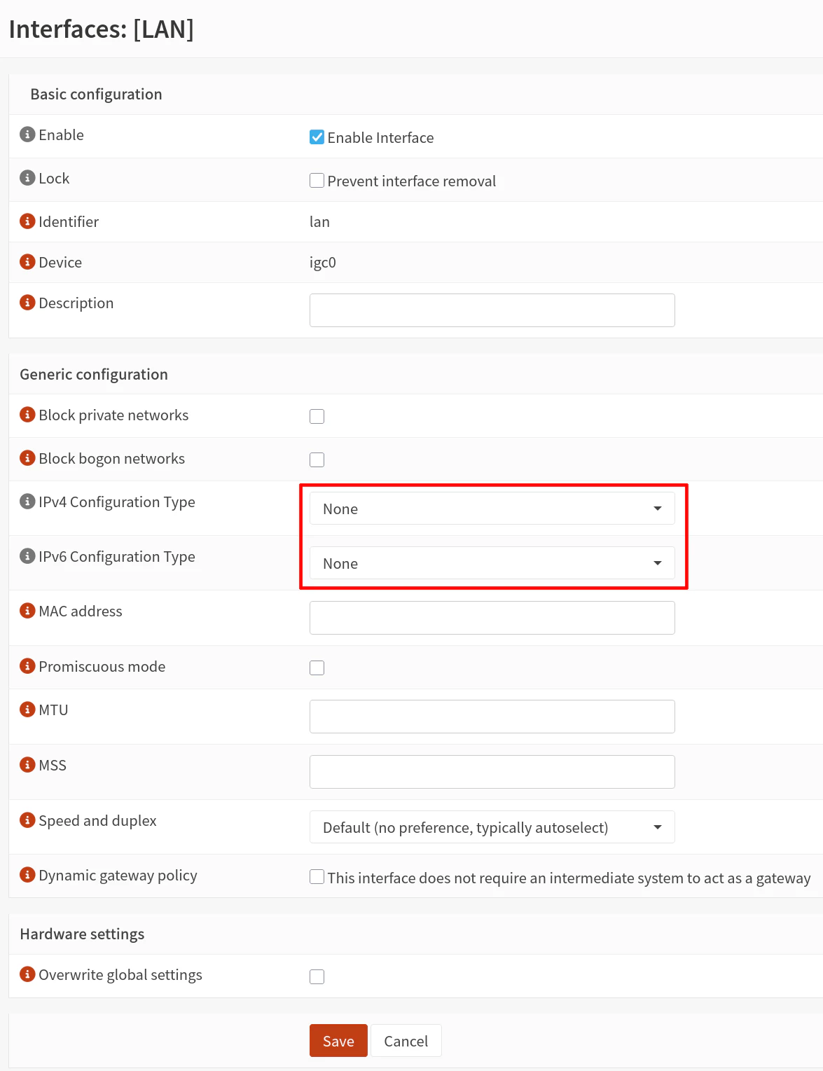
5.9 Disable IP Addresses on LAN Interface
Go to the “Interfaces > [LAN]” page so that the IP addresses can be disabled similar to how it was done for the WAN interface earlier in this guide.
Set the “IPv4 Configuration Type” and “IPv6 Configuration Type” options to None.
5.10 Create a Firewall Rule on Bridge to Allow All Traffic
The last step in configuring the filtering bridge is to create firewall rules. I recommend creating an “allow all” rule to verify traffic can pass through the transparent bridge without issue before implementing stricter firewall rules.
On the “Firewall > Rules > BRIDGE” page, click on the “+” button to add a rule.
Add the following rule to allow all traffic:
| Action | TCP/IP Version | Protocol | Source | Destination | Dest Port | Description | |
|---|---|---|---|---|---|---|---|
| Pass | IPv4+IPv6 | any | any | any | any | Allow all |
Click “Save” and then “Apply changes”.
6. Test the Transparent Bridge
The transparent filtering bridge is ready to be tested on your network!
6.1 Plug Devices into the Bridge Ports
Simply plug an Ethernet cable from your router’s LAN interface to one of the transparent filtering bridge interfaces and another cable from the network switch to the other transparent filtering bridge interface.
Essentially, the OPNsense box will be located in between the router and the network switch where the rest of the devices on your network are located (if you have other devices connected to LAN ports of your router, the traffic from those devices will not be filtered by the transparent filtering bridge).
6.2 (Optional) Create Block Rule to Test Filtering Traffic
If you would like to test blocking traffic with the transparent bridge, you could simply block all HTTPS traffic passing through the bridge (do not worry, you will still have access to the OPNsense web UI).
Create the following block rule above your “allow all” rule on the BRIDGE interface:
| Action | TCP/IP Version | Protocol | Source | Destination | Dest Port | Description | |
|---|---|---|---|---|---|---|---|
| Block | IPv4+IPv6 | TCP | any | any | 443 (HTTPS) | Block HTTPS |
Try accessing any website and you should find that it is blocked (unless you have an existing connection open – firewall states do not clear out automatically by default).
Once you are done testing that block rule, you may disable or remove it so you can access websites again.
7. Allow OPNsense to Access Internet for Updates and Plugins
At this point, your bridge is functional; however, you will notice when you try to update OPNsense that it will fail. The reason is that there is no gateway or DNS configured for the OPNsense system itself.
Even though a static IP address has been configured for the MGMT interface, this configuration does not include the gateway or DNS configuration.
This process is similar to manually specifying a static IP address on a PC where you need to enter the gateway IP address, the PC IP address, the subnet mask, and the DNS server since you are not obtaining all of that information via DHCP.
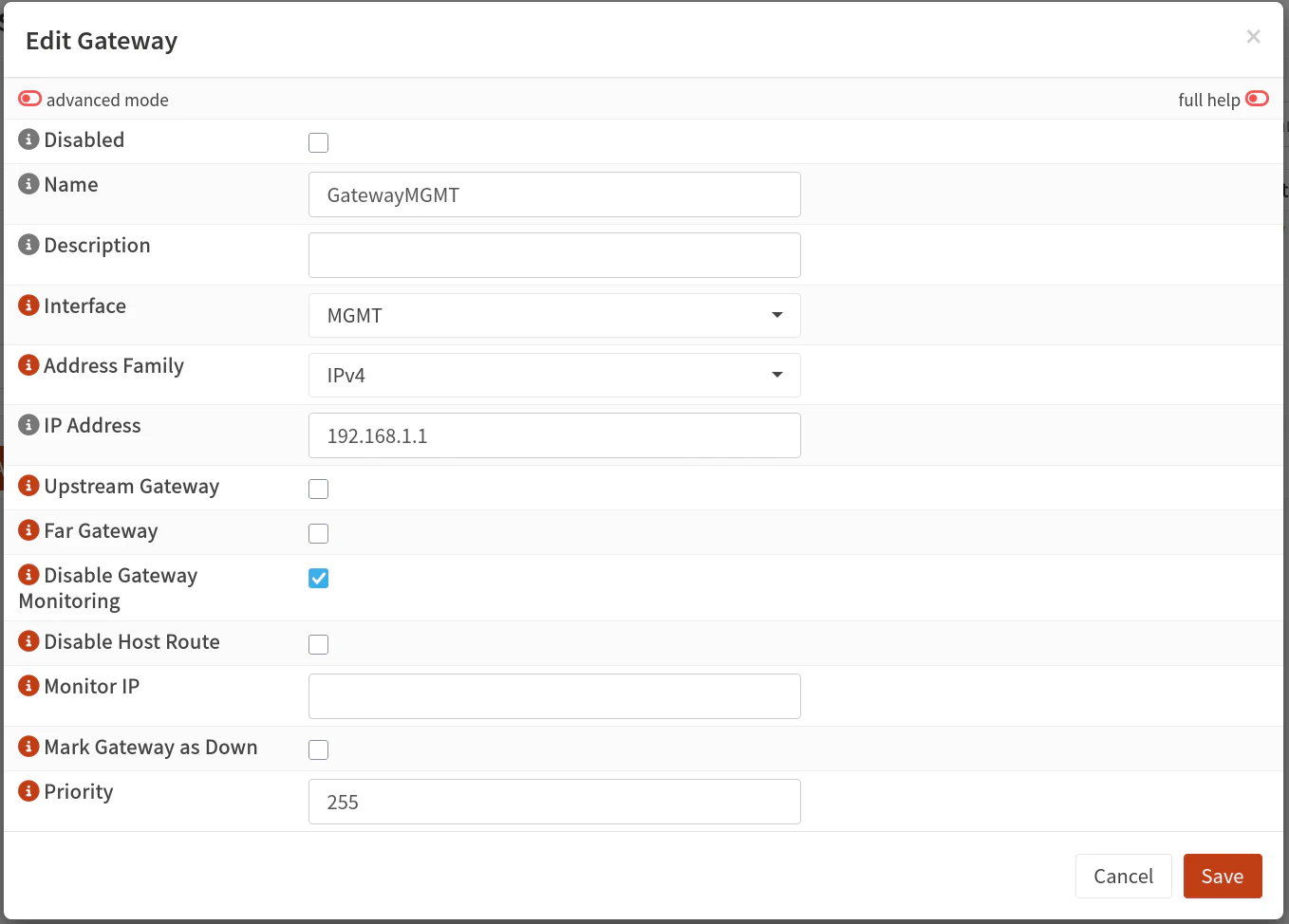
7.1 Create a Gateway
On the “System > Gateways > Configuration” page, click on the “+” button.
Enter a “Name” for the gateway such as GatewayMGMT. Select the “Interface” of MGMT.
Enter the “IP Address” of the primary network’s router IP address such as 192.168.1.1. I have assumed in this guide that your primary network IP address range is 192.168.1.x and the router’s IP address typically is 192.168.1.1.
Click the “Save” button.
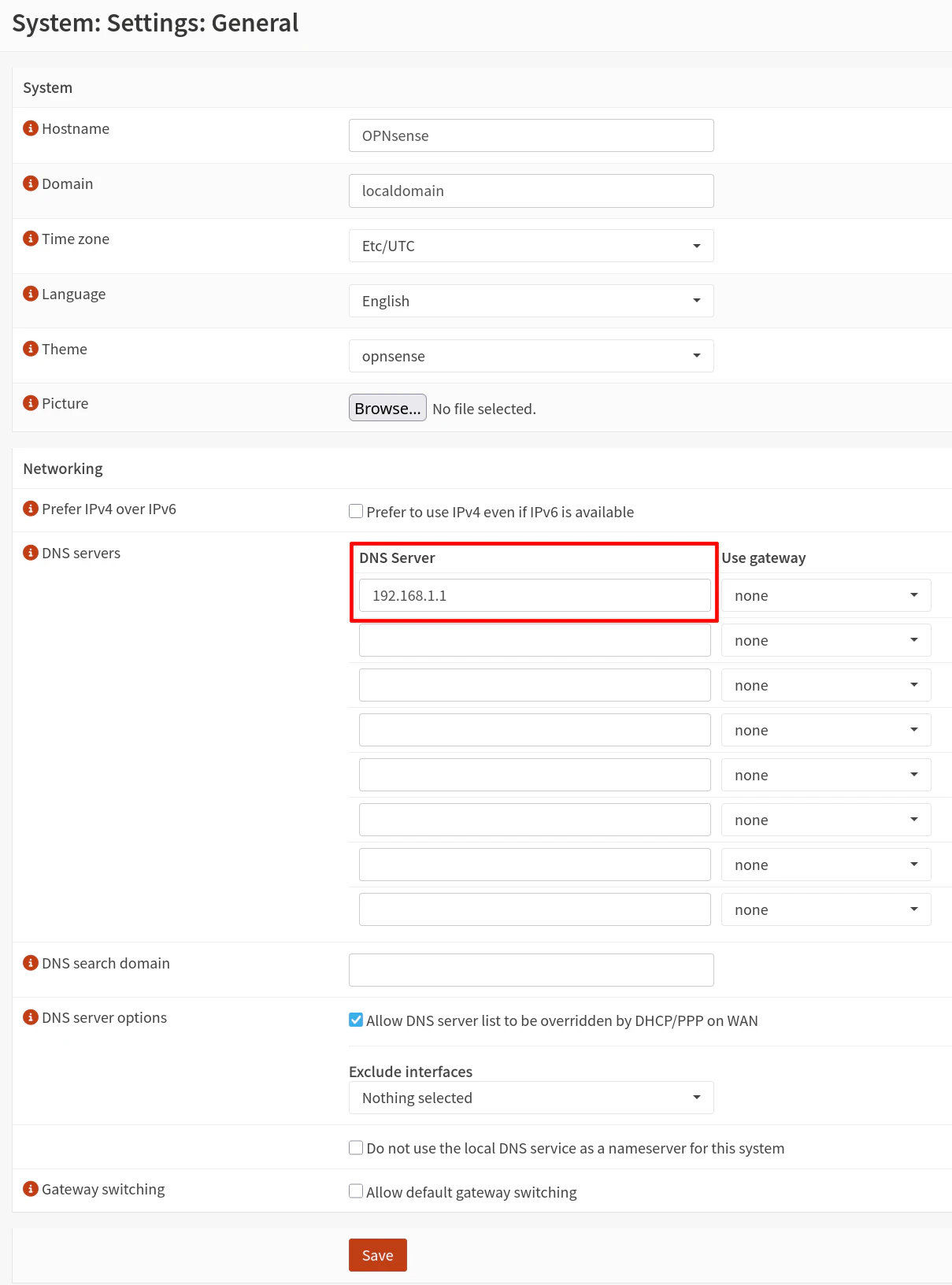
7.2 Add DNS Server to the System DNS Settings
By default, there are no DNS server specified on the “System > Settings > General” page, so you will need to add a DNS server to the list.
Note that the DNS servers listed on this page is what the OPNsense system itself will use for its DNS servers.
Enter 192.168.1.1 to use your primary router’s IP address as the DNS server.
7.3 Update OPNsense and/or Download Plugins
Now you may go to the “System > Firmware > Status” page and click the “Check for updates” button to verify you are able to download updates for OPNsense.
At this time you may install updates if you so desire in order to have the latest bug fixes, security updates, and latest features.
8. Configure Additional Security Features
In addition to using standard firewall rules on the transparent bridge to protect your network, you may configure other security services on your OPNsense system to further improve the security of your network.
Four popular choices are Zenarmor, Suricata, CrowdSec, and Q-Feeds. Each service offers different types of protections.
Zenarmor offers cloud threat intelligence to block ads, apps, and malicious activity. In addition, there are many reports available to help visualize and analyze network traffic. The Free Edition offers a basic set of protections but if you wish to have more security features as well as additional profiles, they offer a Home Edition subscription.
Tip
When using Zenarmor with a transparent filtering bridge, you do not need to set up Zenarmor using “Bridge Mode” since that will bypass the standard OPNsense firewall rules due to how Zenarmor creates the bridge. Therefore you should use the “Routed Mode” for Zenarmor on the transparent filtering bridge so you can still make use of standard firewall rules on the transparent bridge.
Suricata has rulesets that are great for web and application based firewall. However the free rulesets are 30 days old so you will need to pay for the pro rulesets if you wish to block emerging threats. Suricata is useful if you are hosting various applications that are exposed publicly or in environments where you may have untrusted users.
CrowdSec makes use of crowd-sourced malicious IP datasets which may be used to block incoming/outgoing malicious IP addresses (which is more broad and resource efficient than Zenarmor and Suricata). In addition, it offers brute force and other protections for the OPNsense web UI and SSH service. It can also serve as the LAPI (Local API) for other CrowdSec installations on your network.
Q-Feeds provides threat intelligence feeds that can be used to block malicious IP addresses and malicious domains. The malicious domains can be added to the Unbound DNS block lists alongside other blocklists to provide additional DNS blocking. These feeds update every 24 hours but if you want even more frequent updates, you may pay for a Plus license to have updates every 4 hours (or 20 minutes for the Premium license). In addition to IP and domain blocking, Q-Feeds also provides brand protections and dark web monitoring services if you have a Q-Feeds Plus subscription.
Setting up these services on the transparent filtering bridge is very similar to how you normally would set them up when using OPNsense as a standard router/firewall. I have written about Suricata and CrowdSec, which should help get you started!