How to Set Up a Transparent Filtering Bridge on OPNsense 26.1

Photo by Vertigo3d from Getty Images Signature
Table of Contents
Many users have ISP supplied routers or their own gateway/router devices that they must use or prefer to use yet want to add greater security to their networks without replacing their current gateway/router. A transparent filtering bridge allows users to deploy a firewall in their networks while utilizing existing network infrastructure.
This guide will demonstrate how to set up a transparent filtering bridge in OPNsense 26.1 as well as how to set up a few security protections after the bridge has been configured.
If you are using an older version of OPNsense, please refer to my original transparent filtering bridge guide since it includes the configuration for ISC DHCP which is deprecated in 25.7 and newer versions of OPNsense.
Note
The approach to configuring the transparent filtering bridge in this guide is a bit different than the 24.7 guide since I realized there could be a slightly more simplified way to configure the network interfaces which achieves the same end result.
What is a Transparent Filtering Bridge
A transparent filtering bridge is able to inspect network traffic traversing on one physical network interface and forward the traffic to another network interface if it is allowed to pass depending on the firewall rules and other security protections that are in place.
Two physical network interfaces is the minimum number of interfaces you will want to use for a transparent filtering bridge: one for the incoming connection and one for the outgoing connection.
Location of a Transparent Filtering Bridge
There are a number of locations where you might put a transparent filtering bridge on your network depending on where you wish to have additional security protections.
Between the modem and router
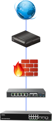
If you have a separate modem/ONT and a separate router, you may put the transparent filtering bridge between your modem and router so the firewall is located at the outermost part of your network.
Some users may want this option if only interested in protecting the perimeter of their networks.
There are a couple of things to note:
-
The source or destination IP address will be the public WAN address of the router so you will not know which device within your network where the traffic is originating from. Therefore you lose some visibility of traffic in your network.
-
While you are able to block traffic entering/leaving your network, you will not be able to block any traffic within your network (between various VLANs, etc.) since the bridge is located before the router’s WAN interface.
Between the router and network switch
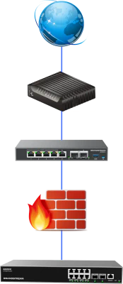
If you have an all-in-one modem/ONT/router or a router/gateway appliance you prefer using instead of OPNsense, you may put the transparent filtering bridge between the router and network switch.
This assumes you are using a router-on-a-stick configuration where everything on the network is connected to the network switch which is connected to the router. If you connect devices to other network interfaces on the router when you have the transparent bridge between the router and switch, the traffic from the devices connected to the router will not be filtered by the bridge.
The great advantage of locating the transparent bridge between the router and network switch is that you can filter traffic within your local network in addition to traffic entering/leaving your network via the WAN interface. You will have greater visibility of your internal network (on various VLANs, etc.) since all of your local routed network traffic must traverse through the router and therefore the transparent bridge.
The example in this guide will use this location for the transparent bridge.
On a single VLAN such as the DMZ network
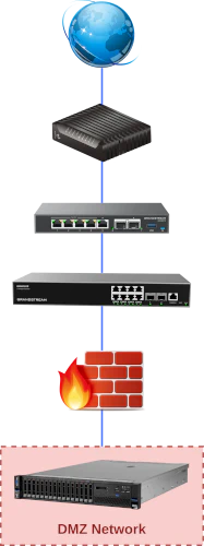
Another possible location you may wish to consider is placing a transparent filtering bridge on a particular VLAN such as a DMZ network.
Even if your primary network router has robust firewall and other security features, you may wish to deploy a second firewall to better protect your local network from the public facing DMZ network.
Businesses may wish to choose to use a different vendor for the secondary firewall to minimize the likelihood that an exploit on one brand of firewall would be exploited on the secondary firewall if it was same vendor.
For home networks, using firewalls of two separate vendors is probably unnecessary from a security standpoint, but you may wish to do so if you enjoy learning how to use different firewall products.
Essentially, you can place a transparent bridge between any two devices on your network. I even tested the transparent filtering bridge between two PCs so that I could test throughput of the Gown R86S-P2 used in my example network. In case you are curious how much CPU you need (for up to 2.5 Gbps networking), I could get 1.8-2 Gbps with Zenarmor enabled with an Intel N5105 CPU, which is pretty good for an older, slower CPU. The R86S-P2 can almost fully saturate 2.5 Gbps.
Example Network
Below is an image of an example network that I will be using in this example. It consists of an existing router (the Grandstream GCC6010), network switch (Grandstream GWN7811P), and wireless access point (Grandstream GWN7664E). There is also a PC on the network (the ZimaBoard 832).

In the example scenario for this guide, I am going to be placing the transparent bridge device between the router and network switch because of the increased visibility of the devices on the network as mentioned earlier.

Warning
Do not plug the OPNsense system into your existing network until you are finished configuring the transparent bridge.
A couple of reasons for not connecting the OPNsense system to the existing network:
-
The default LAN interface has DHCP running and would interfere with the DHCP service running on your existing network.
-
The two transparent bridge interfaces are not yet configured and would take down whatever part of your network where you want the transparent bridge to exist (potentially taking down your entire network).
What is Different about this Guide?
Most transparent filtering bridge guides will demonstrate how to set up a filtering bridge with only two network interfaces. However, I am going to demonstrate using three physical interfaces. I am a big fan of having a dedicated management interface for all my network infrastructure such as the router/firewall, server(s), NAS, and other devices.
One advantage of having a third interface dedicated for management is that you cannot get locked out of the OPNsense web interface while you are configuring the bridge interface. A common problem I often notice is users inadvertently locking themselves out of the web interface – even if the bridge itself may be functioning properly.
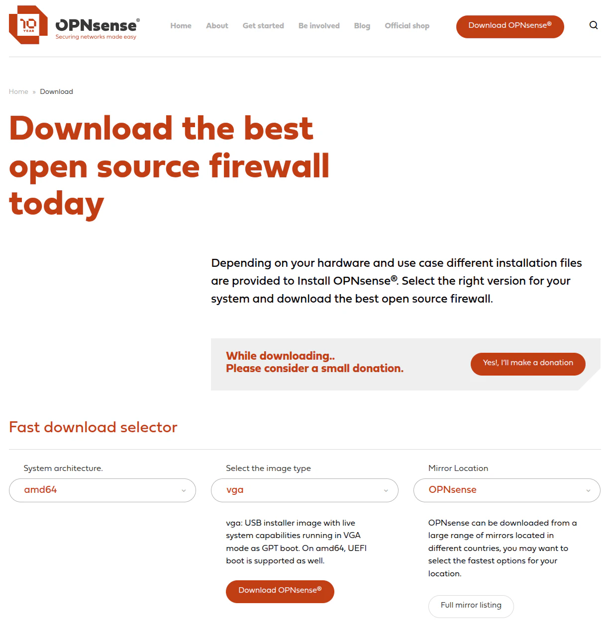
1. Install OPNsense
For the OPNsense installation, you will need to go to the download page of OPNsense and select the VGA image if you wish to image a USB drive for installation OPNsense. You may use software such as Etcher to copy the image to the USB drive.
For this guide, simply let the installer boot without pressing any keys so it uses the default settings for the WAN/LAN interface assignments. Depending on your device will depend on the order of the interfaces. In most cases, OPNsense will default to using the first interface for LAN and the 2nd interface to WAN.
Once you arrive at the login prompt, enter installer as the username and opnsense as the password to install OPNsense.
Then simply follow the normal OPNsense installation process. I will not describe the full process in this guide since I have another guide discussing a basic installation.;’// After the installation is complete, plug your PC into the LAN port and log into the OPNsense web UI at https://192.168.1.1.
Note
You may use the hostname of opnsense.internal instead of the IP address, but since the IP address will be changed later in this guide, the old IP address may be cached for the hostname so it may not immediately work when changing IP addresses.
2. Configure the Default LAN Interface to be the MGMT Interface
Many home users are using the default network IP address of 192.168.1.1/24 (which is 192.168.1.1-192.168.1.254). I am going to assume that scenario for this guide.
If you are not using this IP address range or planning to connect the MGMT interface on a different subnet, you will need to set the MGMT interface to an IP address within that IP address range.
On the original transparent filtering bridge guide, I recommended creating a new interface to be the MGMT interface and testing it before repurposing the original LAN/WAN interfaces to be configured as part of the bridge interface. The main reasoning behind this approach is to ensure the MGMT interface works properly before configuring the other interfaces (minimizes getting locked out due to a misconfiguration).
In this updated guide, I am going to show how to change the default LAN interface to be the MGMT interface, which should simplify some of the steps in the guide. There is a very small risk of locking yourself out if you deviate from the instructions in this guide, but there is always such a risk when configuring interfaces and firewall rules.
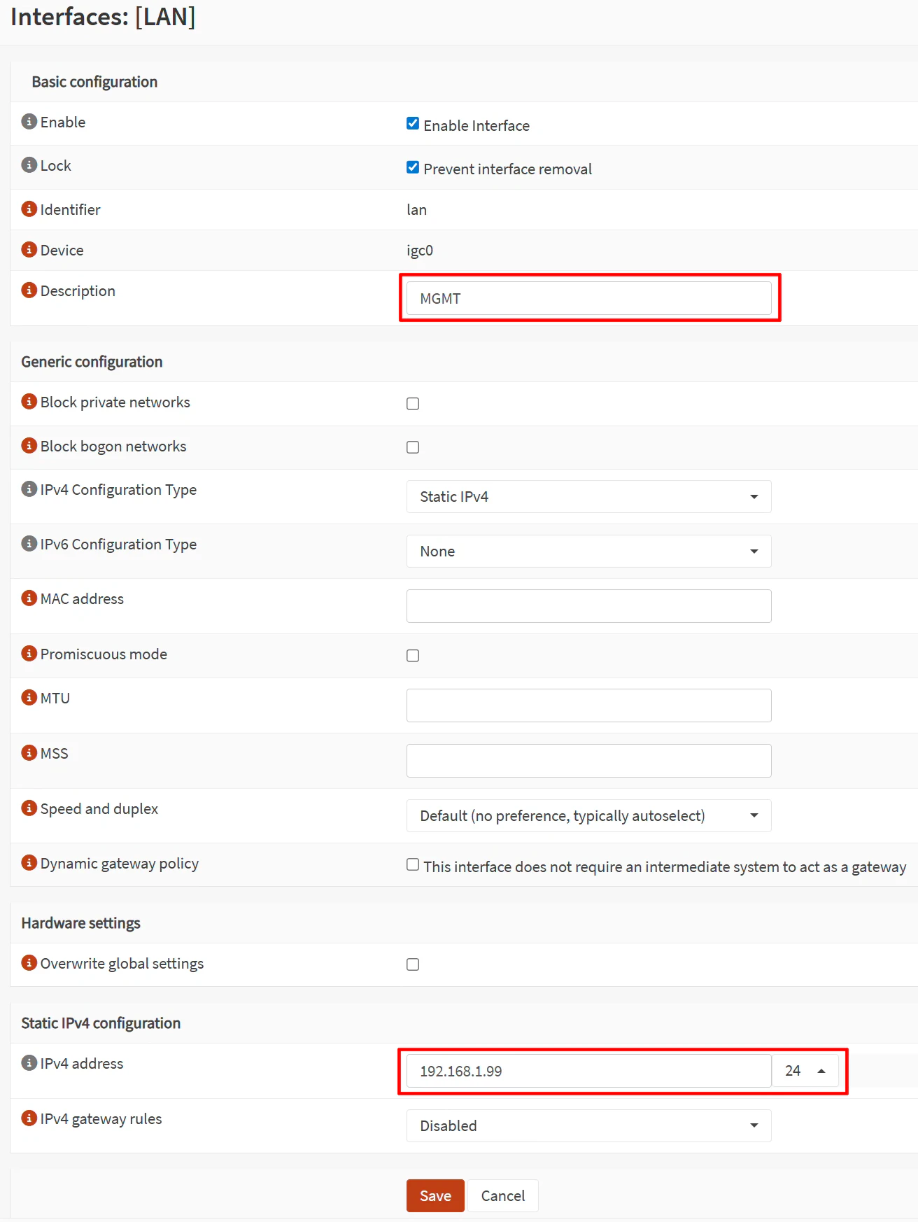
2.1 Rename LAN Interface and Change IP Address
On the “Interfaces > [LAN]” page, go to the “Static IPv4 configuration” section at the bottom of the page.
Update the following values:
| Option | Value |
|---|---|
| Description | MGMT |
| IPv4 address | 192.168.1.99 |
| IPv6 Configuration Type | None, if not using IPv6 |
For the rest of the guide I will be referring to the MGMT interface instead of LAN interface since it has been renamed.
I am using an IP address such as 192.168.1.99 to avoid conflicting with 192.168.1.1 IP address of your main network when you eventually connect the MGMT interface to your existing network. Make sure the IP address is outside of the range of DHCP of your existing router to avoid potential IP address conflicts.
Click the “Save” button and click “Apply changes”.
You will get disconnected from the web UI and will need to log back into OPNsense.
2.2 Log Back into OPNsense
Log back into OPNsense using the new IP address https://192.168.1.99 to continue the rest of this guide.
2.3 Create a Gateway
Since there is not going to be a WAN interface when the transparent filtering bridge is fully configured, you will need to set up a gateway for the MGMT interface so that the OPNsense system can access the Internet for updates.
This process is similar to manually specifying a static IP address on a PC where you need to enter the gateway IP address, the PC IP address, the subnet mask, and the DNS server since you are not obtaining all of that information via DHCP.
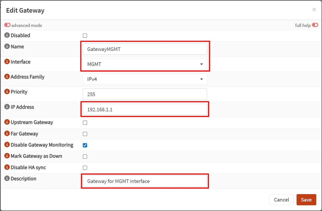
On the “System > Gateways > Configuration” page, click on the “+” button.
Update the following values:
| Option | Value |
|---|---|
| Name | GatewayMGMT |
| Interface | MGMT |
| IP Address | 192.168.1.1 |
| Description | Gateway for MGMT interface |
The “IP Address” should be set to the primary network’s router IP address such as 192.168.1.1. I have assumed in this guide that your primary network IP address range is 192.168.1.x and the router’s IP address typically is 192.168.1.1.
Click the “Save” button.
2.4 Add DNS Server to the System DNS Settings if Unbound DNS is Disabled
By default, Unbound DNS is listening on all of the interfaces on OPNsense. If you leave Unbound DNS enabled, you should be able to have DNS resolution for the OPNsense system since it will use the Unbound DNS service as a recursive DNS resolver.
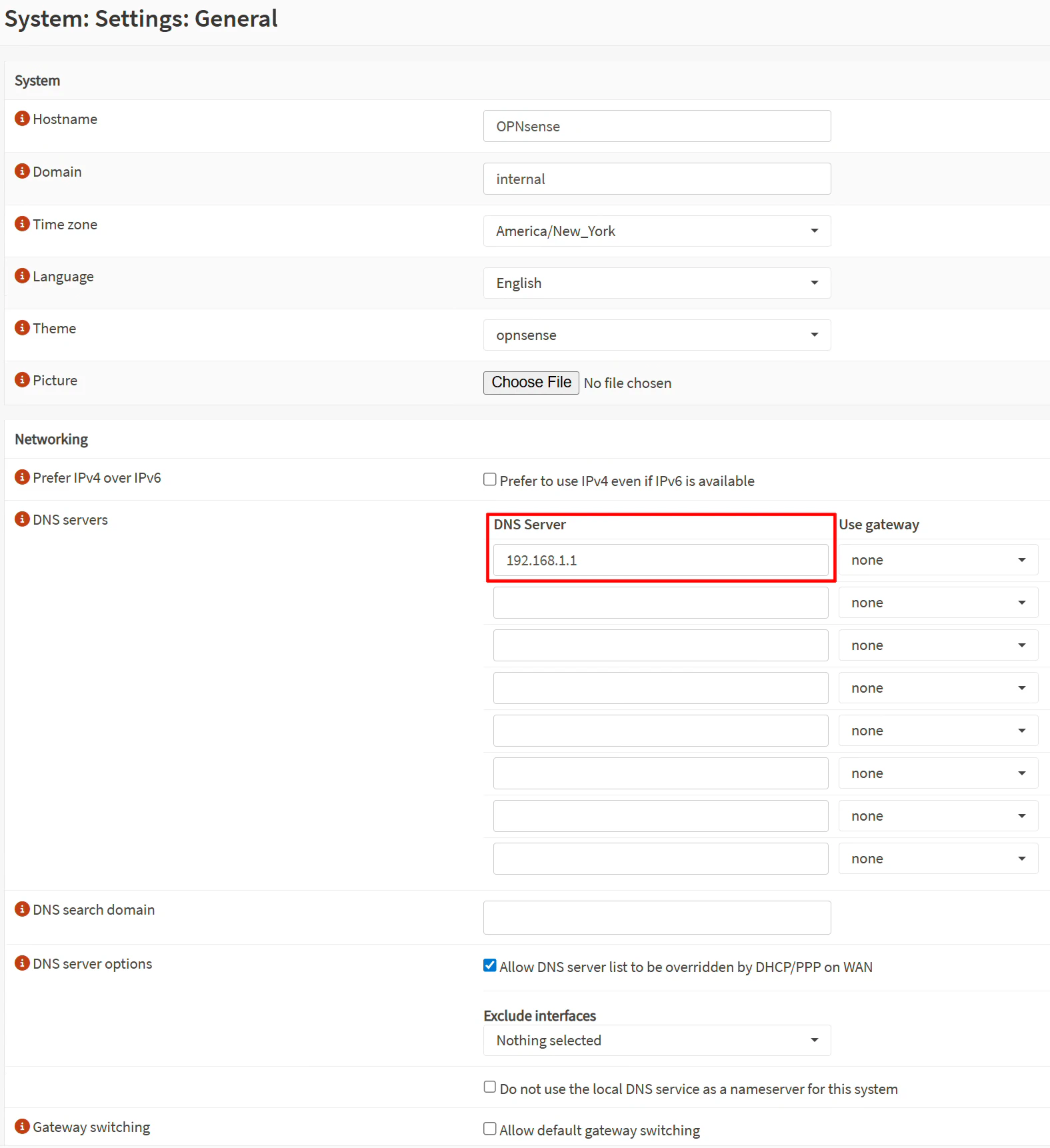
However, if you wish to disable Unbound DNS on the OPNsense system to free up a small amount of system resources, you do not wish to use a recursive DNS resolver for the OPNsense system, or you wish to use the router or other DNS server on your existing network, you may specify the DNS server on the “System > Settings > General” page after disabling Unbound DNS.
The DNS servers listed on this page is what the OPNsense system itself will use for its DNS servers.
On the “System > Settings > General” page, enter 192.168.1.1 to use your primary router’s IP address as the DNS server.
2.5 (Optional) Tighten up the MGMT Firewall Rules
In OPNsense 26.1, there is a new firewall rules user interface. If you are setting up the transparent bridge from a fresh installation of OPNsense 26.1, I recommend migrating the rules to the new user interface page so that you will not have to do it later when OPNsense may force you to switch when the old page is removed.
To do the migration, follow the steps on the “Firewall > Rules > Migration Assistant” page. In short, click “Export current rules” to save the rules to a CSV file. Then click the “Import rules using the button in the grid footer” to take you to the “Firewall > Rules [new]” page. Click on the import csv button at the bottom of the table. Import the file and you should see both of the default IPv4 and IPv6 allow all rules. Once the rules are listed, click on the “Remove all legacy rules” on the “Firewall > Rules > Migration Assistant” page.
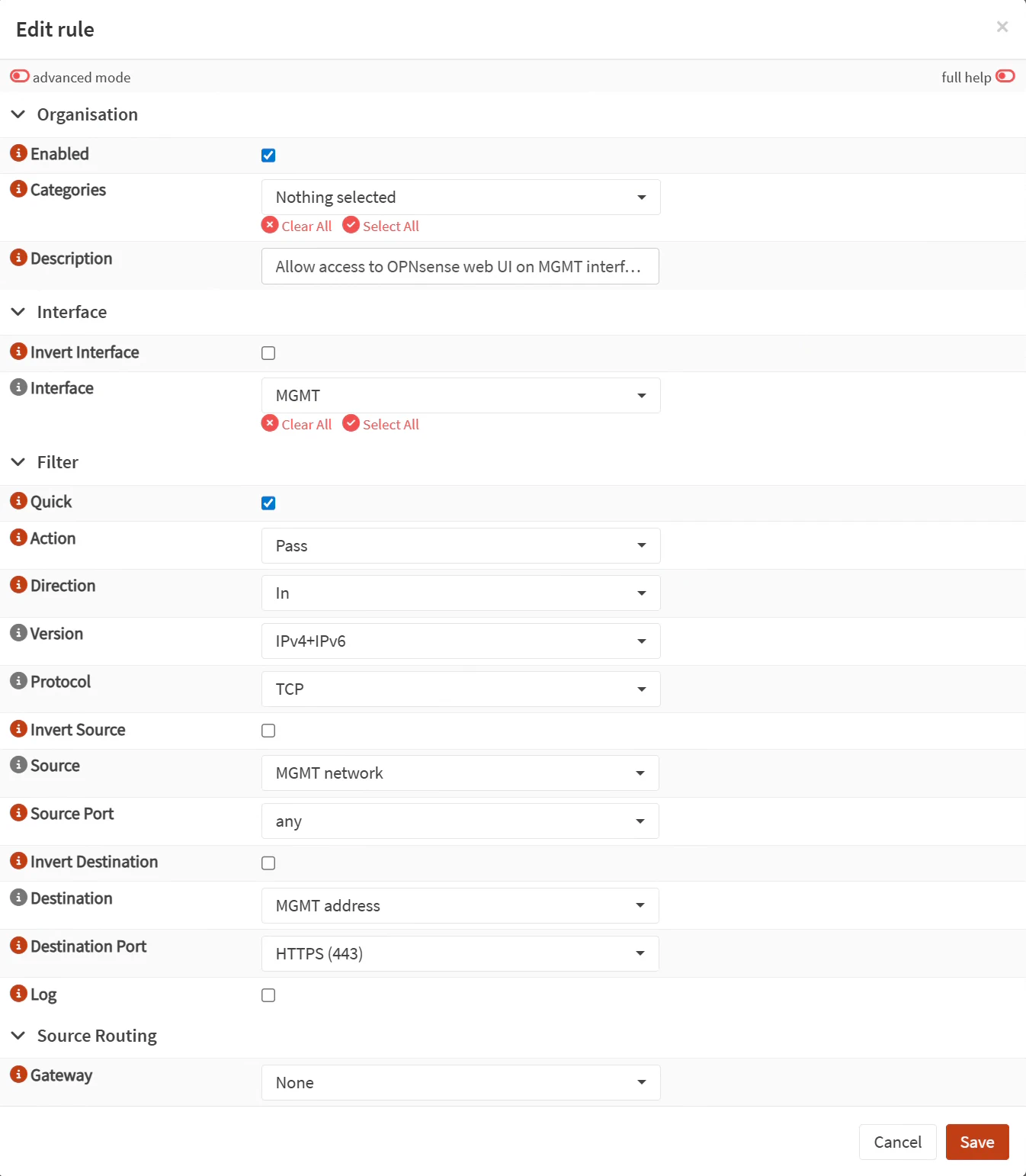
Edit the default IPv4 allow all rule:
| Option | Value |
|---|---|
| Description | Allow access to OPNsense web UI on the MGMT interface |
| Version | IPv4+IPv6 (can do both protocols if IPv6 is being used) |
| Protocol | TCP |
| Destination | MGMT address |
| Destination port | HTTPS (443) |
If you wish to have SSH access enabled, you could create a firewall alias and add both port 443 and 22 to the alias and use that alias for the “Destination port”.
Since IPv6 was added to the IPv4 rule, you may remove the default IPv6 allow all rule. Even if you do not currently utilize IPv6, it does not hurt to include it in the firewall rule in case you enable it later or it becomes available on your network.
Click “Apply” to apply the firewall changes.
3. Configure the New Interfaces to be Used in the Bridge
Now that the MGMT interface is configured, you are ready to configure the interfaces that are going to be used in the filtering bridge.
3.1 Delete the Original WAN Interface
The original WAN interface is not going to be used in a transparent bridge configuration.
Rather than reconfigure the WAN interface to be used in the bridge (as was done in the original guide), the WAN interface can simply be removed since it is easy enough to create new interfaces for the bridge (also, you may want to use a different physical interface for the bridge).
On the “Interfaces > Assignments” page, click the trash icon beside the WAN interface to delete it.
3.2 Assign the First Interface for Use in the Bridge
While still on the “Interface > Assignments” page, select an interface such as igc1 (interface names may vary depending on your hardware).
For the “Description”, enter a name to help identify the purpose of the physical interface. I am going to use ROUTER_SIDE to indicate this bridged interface will be connected to the router.
Click the “Add” button.
3.3 Assign the Second Interface for Use in the Bridge
For the second interface that will be added to the bridge, follow the same process. Select an interface such as igc2.
A good “Description” for this interface would be SWITCH_SIDE to indicate this interface will be connected to your main network switch.
Click the “Add” button.
3.4 Enable the interfaces for use in the bridge
After the interfaces are assigned, they need to be enabled.
To enable the interfaces, visit the “Interfaces > [ROUTER_SIDE]” page and check “Enable interface” and “Prevent interface removal”. Click “Save”.
Do the same for the second interface: visit “Interfaces > [SWITCH_SIDE]” and check “Enable interface” and “Prevent interface removal”. Click “Save”.
Finally, click “Apply changes” to apply all interface changes.
4. Configure the Transparent Filtering Bridge
The steps in this section follow relatively closely to the OPNsense instructions with a few minor differences. Since a separate, physical MGMT interface has already been configured, you will be able to skip the OPNsense instructions on configuring a management interface on the filtering bridge interface.
4.1 Disable Outbound NAT Generation
Because OPNsense is going to operate as a filtering bridge rather than as a router, you can disable outbound NAT.
On the “Firewall > NAT > Outbound” page, click the radio button for “Disable outbound NAT rule generation”.

Click “Save” and “Apply changes”.
4.2 Modify the System Tunable Options
Next navigate to the “System > Settings > Tunables” page since a couple of system tunables need to be modified.
Click on the search box at the top of the tunables table.
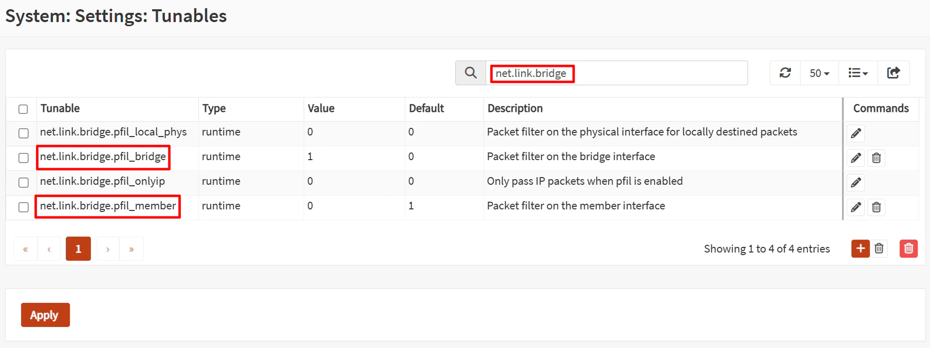
Search for the text net.link.bridge.pfil_bridge. Click on the pencil icon to edit the entry. Enter 1 for the value to enable filtering on bridge interfaces. When you are done, click “Save”.
When you return to the tunable page, search for the next tunable net.link.bridge.pfil_member, click on the pencil icon, and enter 0 for the value. Click “Save”. This will disable filtering on the individual physical interfaces.
Click “Apply” at the bottom of the page.
Since these are runtime tunables, you do not need to reboot for the changes to take effect.
4.3 Create the Bridge Interface
Visit the “Interfaces > Devices > Bridge” page. Click on the “+” button to add a bridge interface.
For the “Member interfaces”, you will need to select ROUTER_SIDE and SWITCH_SIDE. You can be creative with the “Description” or simply call it BRIDGE.
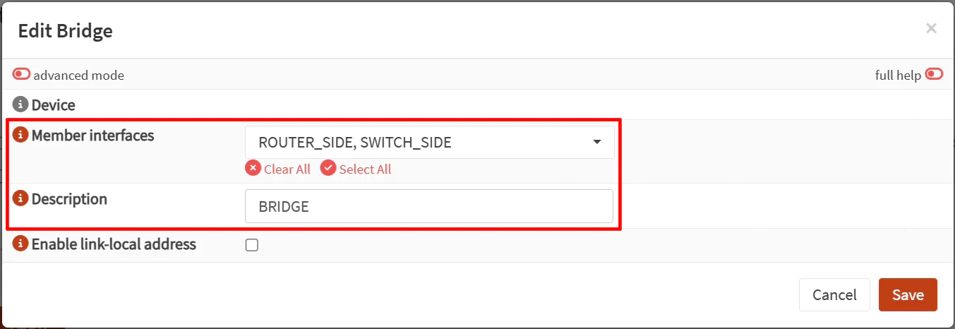
Click “Save” and click “Apply” to apply the changes.
4.4 Assign the Bridge Interface
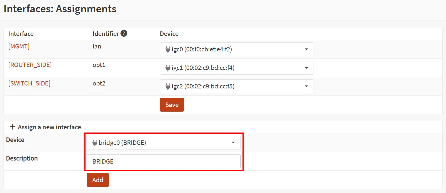
On the “Interfaces > Assignments” page, select the bridge for the “Device” from the dropdown. The value will be called bridge0 (BRIDGE).
Enter a “Description” for the interface such as BRIDGE. This will be the value that shows up on the left side menu and other places for the interface name so I recommend entering a useful, short name.
Click the “Add” button.
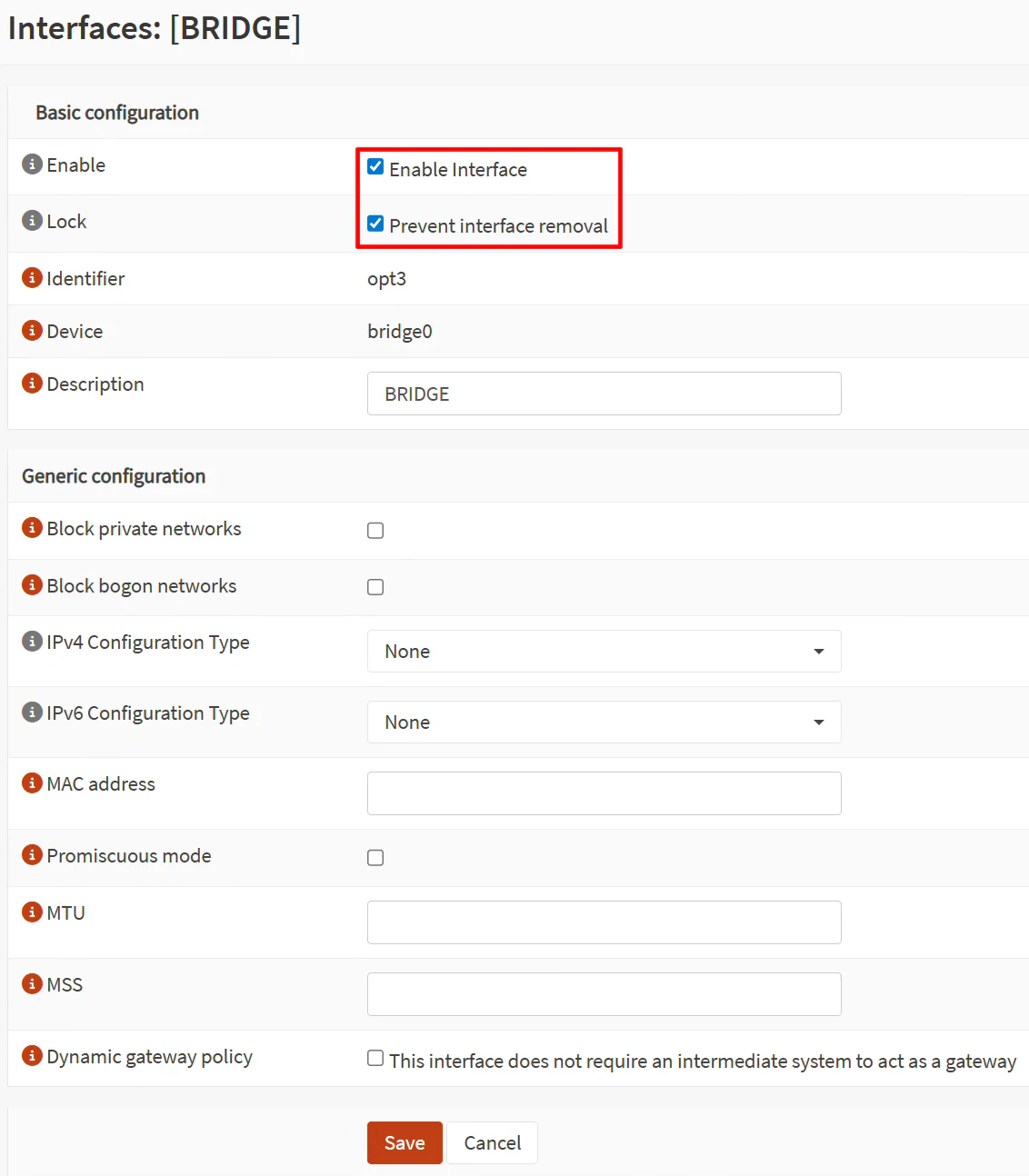
4.5 Enable the Bridge Interface
Now the bridge interface can be enabled by going to the “Interfaces > [BRIDGE]” page. Click the checkbox for “Enable Interface” as well as “Prevent interface removal”.
Leave everything at the default values.
Click “Save” and “Apply changes”.
4.6 Create a Firewall Rule on Bridge to Allow All Traffic
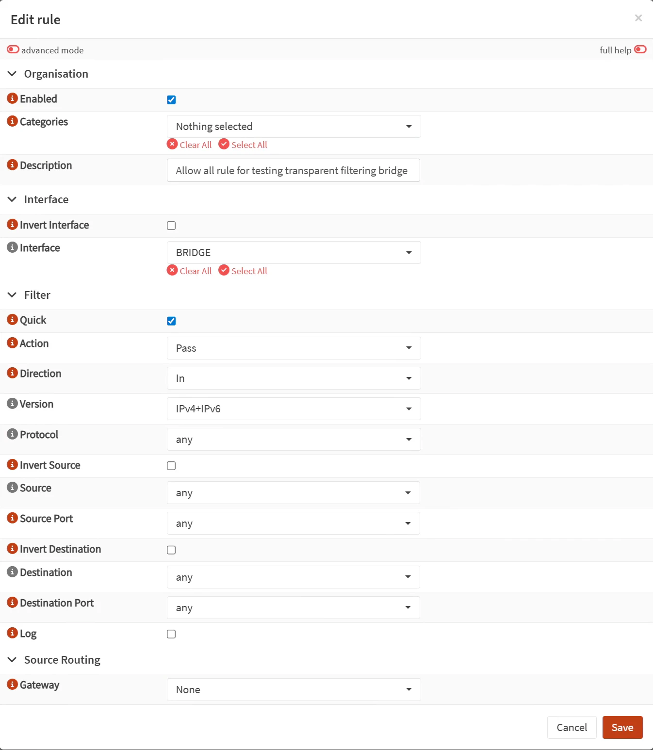
The last step in configuring the filtering bridge is to create firewall rules. I recommend creating an “allow all” rule to verify traffic can pass through the transparent bridge without issue before implementing stricter firewall rules.
On the “Firewall > Rules [new]” page, click on the “+” button to add a rule.
Add the following rule to allow all traffic:
| Option | Value |
|---|---|
| Description | Allow all rule for testing transparent filtering bridge |
| Interface | BRIDGE |
| Action | Pass |
| Version | IPv4+IPv6 (can do both protocols if IPv6 is being used) |
| Protocol | any |
| Source/Destination | any |
| Source Port/Destination Port | any |
Click “Save” and then “Apply”.
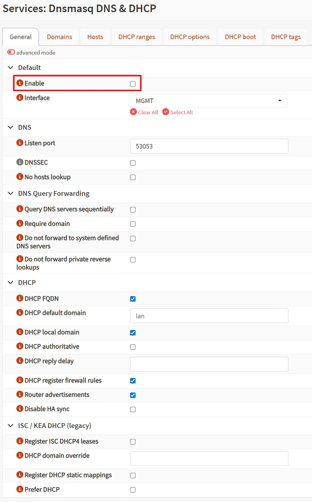
5. Disable DHCP on the MGMT Interface
Since the MGMT was the original LAN interface, the DHCP service is currently running on the MGMT interface. DHCP is no longer necessary on the MGMT interface because DHCP will be running on the router powering the main network where the MGMT interface will be connected (you do not want to have 2 DHCP servers running on the same network!). Therefore, DHCP can be disabled.
On the “Services > Dnsmasq DNS & DHCP” page, uncheck “Enable”.
Click “Save”.
6. Connect the OPNsense System to the Existing Network
Now that the DHCP service is disabled on the MGMT interface, the OPNsense system is ready to be connected to your main network!
6.1 Plug the MGMT Interface into Existing Network
With the DHCP service disabled on the MGMT interface, it is safe to connect it to your existing network. You no longer need to have a system plugged directly into the OPNsense system to configure it. You may plug your PC back into the network as well.
You should be able to access the OPNsense web UI with the same 192.168.1.99 IP address or hostname you have configured for the OPNsense system from any device on the same network where the MGMT interface is connected.
6.2 Plug Devices into the Bridge Ports
Simply plug an Ethernet cable from your router’s LAN interface to the transparent filtering bridge interface you defined as ROUTER_SIDE and another cable from the SWITCH_SIDE interface to the network switch.
Essentially, the OPNsense box will be located in between the router and the network switch where the rest of the devices on your network are located (if you have other devices connected to LAN ports of your router, the traffic from those devices will not be filtered by the transparent filtering bridge).
7. Test the Transparent Bridge
The transparent filtering bridge is ready to be tested on your network!
7.1 Verify Network Connectivity of Devices Behind the Bridge
Once the router and switch is connected to the filtering bridge interfaces, a quick test is trying to access any website in your web browser. If you can get access, that should be enough to verify that the bridge is working properly since traffic is passing through the bridge.
You may also take a look at the “Live View” page under “Firewall > Log Files > Live View”. You will see traffic that is being allowed or denied. A filter may be applied to only show the BRIDGE interface traffic so it is more clearly visible.
7.2 (Optional) Create Block Rule to Test Filtering Traffic
If you would like to test blocking traffic with the transparent bridge, you could simply block all HTTPS traffic passing through the bridge (do not worry, you will still have access to the OPNsense web UI).
Create the following block rule above your “allow all” rule on the BRIDGE interface:
| Option | Value |
|---|---|
| Description | Block HTTPS |
| Interface | BRIDGE |
| Action | Block |
| Version | IPv4+IPv6 |
| Protocol | TCP |
| Source/Destination | any |
| Destination Port | HTTPS (443) |
Try accessing any website from a device behind the filtering bridge, which is any device connected to the network switch and you should find that it is blocked (unless you have an existing connection open – firewall states do not clear out automatically by default).
Once you are done testing that block rule, you may disable or remove it so you can access websites again.
8. Configure Additional Security Features
In addition to using standard firewall rules on the transparent bridge to protect your network, you may configure other security services on your OPNsense system to further improve the security of your network.
Four popular choices are Zenarmor, Suricata, CrowdSec, and Q-Feeds. Each service offers different types of protections.
Zenarmor offers cloud threat intelligence to block ads, apps, and malicious activity. In addition, there are many reports available to help visualize and analyze network traffic. The Free Edition offers a basic set of protections but if you wish to have more security features as well as additional profiles, they offer a Home Edition subscription.
Tip
When using Zenarmor with a transparent filtering bridge, you do not need to set up Zenarmor using “Bridge Mode” since that will bypass the standard OPNsense firewall rules due to how Zenarmor creates the bridge. Therefore you should use the “Routed Mode” for Zenarmor on the transparent filtering bridge so you can still make use of standard firewall rules on the transparent bridge.
Suricata has rulesets that are great for web and application based firewall. However the free rulesets are 30 days old so you will need to pay for the pro rulesets if you wish to block emerging threats. Suricata is useful if you are hosting various applications that are exposed publicly or in environments where you may have untrusted users.
CrowdSec makes use of crowd-sourced malicious IP datasets which may be used to block incoming/outgoing malicious IP addresses (which is more broad and resource efficient than Zenarmor and Suricata). In addition, it offers brute force and other protections for the OPNsense web UI and SSH service. It can also serve as the LAPI (Local API) for other CrowdSec installations on your network.
Q-Feeds provides threat intelligence feeds that can be used to block malicious IP addresses and malicious domains. The malicious domains can be added to the Unbound DNS block lists alongside other blocklists to provide additional DNS blocking. These feeds update every 24 hours but if you want even more frequent updates, you may pay for a Plus license to have updates every 4 hours (or 20 minutes for the Premium license). In addition to IP and domain blocking, Q-Feeds also provides brand protections and dark web monitoring services if you have a Q-Feeds Plus subscription.
Setting up these services on the transparent filtering bridge is very similar to how you normally would set them up when using OPNsense as a standard router/firewall. I have written about Suricata and CrowdSec, which should help get you started!