Set Up a Management VLAN for OPNsense, a Network Switch, and a Wireless Access Point

Photo by SmileStudioAP from iStock
Table of Contents
In my previous guides which mention the purpose and importance of a management network/VLAN, I used the default VLAN 1 for the management network to simplify the configuration of the management network because most devices default to the untagged VLAN 1 network.
In my network, I use the default untagged VLAN 1 network (the default LAN in OPNsense) as my management network. When taking this approach, one must be careful to keep devices off of the default VLAN by assigning all other ports to various VLANs– even ports which are not currently being used (in case someone plugs a devices into an unused wall jack, for instance). The idea is to prevent unauthorized access to the management network.
For a home network, this is simple enough to manage. However, in a business environment, it is best to create a separate management VLAN to manage all critical network infrastructure since you can put firewall(s) in place to protect that the management VLAN from unauthorized access.
Many home users may wish to create a dedicated management VLAN as well for learning purposes and/or to mimic best security practices of enterprise environments. As you will see when working through this process, there are additional steps which are necessary when creating a dedicated management VLAN compared to using the default untagged VLAN 1 network.
Tip
Ideally, you should not change the VLAN configuration of the current interface you are connected to so you do not inadvertently lock yourself out of OPNsense or your network switch. You need to make sure the management VLAN is configured properly before cutting completely over to that network. Once the management VLAN is configured properly, you may stop using the default VLAN 1 network as your management network.
I will be using an OPNsense virtual machine (but you can use any mini-PC network appliance (affiliate link) ), a TP-Link T2600G-28MPS switch (affiliate link) , and a Grandstream GWN7660 wireless AP (affiliate link) to demonstrate the process.

OPNsense Configuration
Let us start with the OPNsense configuration. In this example, I am going to be using the LAN interface as the physical interface for the management (MGMT) VLAN. Ensure that your PC/laptop is connected to the LAN interface at all times until it is time to test that the MGMT VLAN is configured properly.
OPNsense: Creating MGMT VLAN Interface
The first step is to create a MGMT VLAN. Navigate to the “Interfaces > Other Types > VLAN” page, and click the “+” button to add a new VLAN.
Select the [LAN] network as the “Parent”. In this example, I will use 99 as the “VLAN tag”, but you can use whatever value you prefer (it just needs to be used consistently when you follow this guide). For the “Description” you may enter something like MGMT. Use a name that describes the purpose of the VLAN so you can easily identify it later.
Click the “Save” button.

On the “Interfaces > Assignments” page, you should see the new VLAN at the bottom of the page. Enter a “Description” such as MGMT. This description will be used in the left side menu so choose the desired name.
Click the “Add” button.

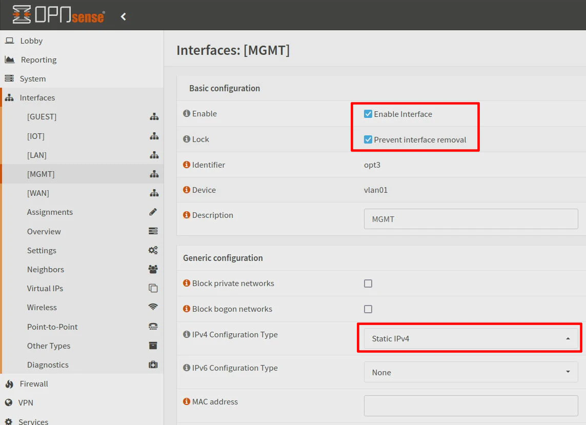
You will need to configure the new interface. Go to the “Interfaces > [MGMT]” page to enter the configuration. Click on “Enable Interface” so the interface will be enabled and “Prevent interface removal” if you wish to reduce the likelihood of accidentally deleting the interface.
For the “IPv4 Configuration Type”, select Static IPv4 from the dropdown.
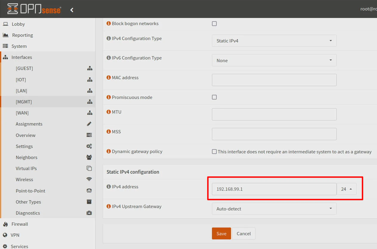
In the “Static IPv4 configuration” section at the bottom of the page, enter 192.168.99.1 for the interface address and 24 for the network size (CIDR notation).
Click “Save”.
Your management interface has now been created!
OPNsense: Configuring DHCP
Most likely you will want DHCP enabled on your MGMT network for devices where you do not need a static IP such as a PC/laptop (or Raspberry Pi) that you will use to manage all your network infrastructure.
Visit the “Services > ISC DHCPv4 > [MGMT]” page. Click the “Enable DHCP server on the MGMT interface” so DHCP is enabled for the MGMT VLAN. Enter your desired network range for DHCP such as 192.168.99.100-192.168.99.199.
Click the “Save” button.

OPNsense: Adding Firewall Rules
Whenever you create a new network, by default there are no firewall rules on that interface so all traffic will be blocked, which is not what you will want. To save time creating new rules, you can clone existing rules of other network interfaces to isolate your local networks. You will need to change all of the references to MGMT instead of LAN or whatever the interface name is if you decide to clone existing rules.
You will also need an additional firewall rule on the MGMT interface to allow access to the OPNsense web interface if you have a rule which blocks all private IP addresses (to isolate the MGMT VLAN from other VLANs). Allowing HTTPS on the MGMT interface IP address is sufficient, but if you would like HTTP to be redirected to HTTPS, you should also allow HTTP.
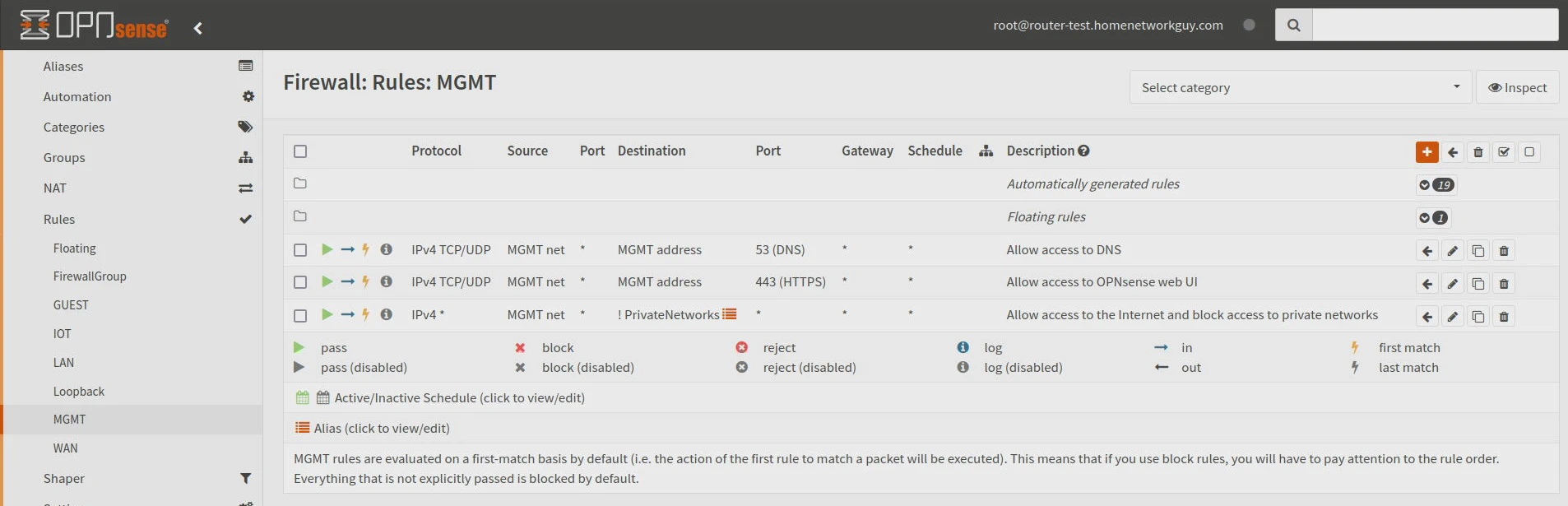
Below are the firewall rules you will need to add. Note that PrivateNetworks is a firewall rule alias containing all of the private IPv4 networks (10.0.0.0/8,172.16.0.0/12,192.168.0.0/16).
| Action | TCP/IP Version | Protocol | Source | Dest / Invert | Destination | Dest Port | Description |
|---|---|---|---|---|---|---|---|
| Pass | IPv4 | TCP/UDP | MGMT net | unchecked | MGMT address | 53 (DNS) | Allow access to DNS |
| Pass | IPv4 | TCP | MGMT net | unchecked | MGMT address | 443 (HTTPS) | Allow access to OPNsense web UI |
| Pass | IPv4 | any | MGMT net | checked | PrivateNetworks | any | Allow access only to Internet |
Switch Configuration
Once OPNsense has been configured, it is time to configure VLANs on the network switch. The configuration of the network switch is critical in ensuring VLANs will function as expected.
Switch: Create MGMT VLAN
I am going to assume you have a factory reset/default TP-Link L2 managed switch. The default IP address is 192.168.0.1. You will need to temporarily change your IP address of your PC/laptop to be on the same network such as 192.168.0.10. The subnet mask needs to be 255.255.255.0.
Once you have changed your system’s IP address, access the web interface via https://192.168.0.1.
Go to the “L2 Features” page and click on “VLAN > 802.1Q VLAN”. Click the “Add” button.
Enter the “VLAN ID” of 99 and the “VLAN Name” of MGMT. Under the “Untagged Ports” section, select Port 3 so that you have a port on the MGMT VLAN where you can test if your PC/laptop is able to connect to the MGMT VLAN. Also select Port 21, which is where the wireless access point is connected. The reason you want Port 21 included in the “Untagged Ports” is that you are wanting the untagged traffic coming from the wireless AP to be on the MGMT VLAN. This will allow you to access the web interface of the AP from the MGMT VLAN (if the AP gets an IP addressed assigned via DHCP, it will be assigned an IP address on the MGMT VLAN).
For the “Tagged Ports” section, you will want to include Port 23 which is the port connected to OPNsense. This will allow the MGMT traffic through the interface.
Click the “Create” button to save the VLAN configuration.

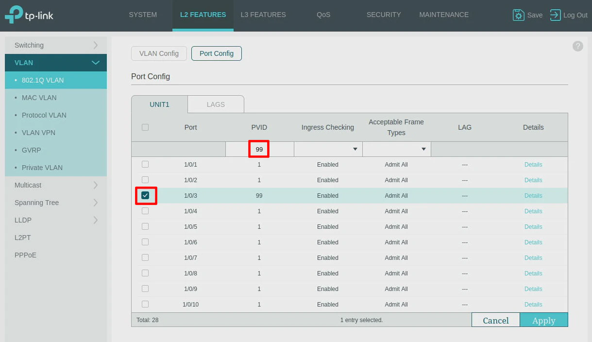
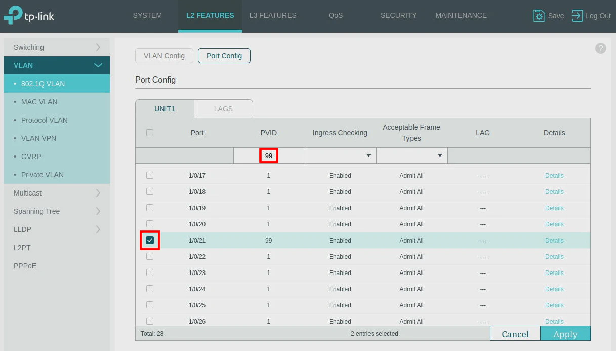
One step that is critical with TP-Link switches is to set the “PVID”. This trips up many TP-Link users including myself. Most modern switches will automatically set the appropriate “PVID” based on the VLAN assigned on the port assignments.
Go to the “Port Config” tab at the top of the page and select Port 3 and Port 21 as shown in the screenshots below. Then enter 99 as the “PVID”. Click the “Apply” button.
Switch: Create MGMT Interface for Web UI
But what about the network switch’s web interface? To access the web interface of the switch on the MGMT VLAN, you can simply create a new interface. On the “L3 Features > Interface” page, click on the “Add” button.
Note
Only the L2 managed TP-Link switches have the “Interface” option. Smart managed TP-Link switches have different options to set the management VLAN.
Enter 99 for the “Interface ID”. Select Static for the “IP Address Mode”. Enter 192.168.99.2 as the IP address (it can be any IP address that is not in your DHCP range you defined in OPNsense). The “Subnet Mask” should be 255.255.255.0. You may optionally enter an “Interface Name” of Management so you know the purpose of the interface you just created.
Click the “Create” button to save the interface settings. You should now be able to access the network switch from the MGMT network.

Tip
Do not click the “Save” button at the top of the page until you verify your switch configuration is working properly. If you messed up your switch configuration and are locked out of your switch, you may reboot the switch to restore the configuration to a previous state. However, you must remember to click “Save” when everything is working so that you do not lose all your configuration you just completed!
Wireless AP Configuration
For the Grandstream wireless access point, moving the management interface to the MGMT VLAN is more of a matter of proper network switch configuration since Port 21 on the switch was configured to be on VLAN 99.
If you already had your wireless AP plugged into the switch when you configured the VLANs, you may need to unplug it and plug it back in for it to pick up the new IP address in the management VLAN.
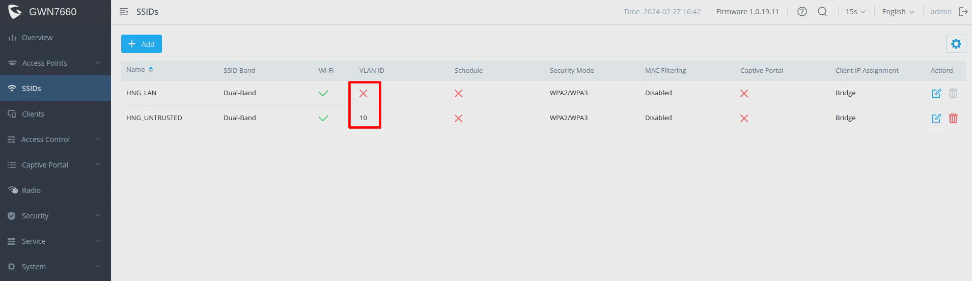
You should be able to create SSIDs as shown below that belong to different VLANs without issue even though you assigned Port 21 to be on the MGMT VLAN (since that was for the untagged traffic).
In order to make use of multiple SSIDs assigned to different VLANs, you will need to add the VLANs to port 21 on the switch as “tagged port” members so that the tagged traffic will pass through. Be sure to leave the default “Frame type” to “admit all”.
Note
In the screenshot below, if you do not specify a VLAN for a SSID, the clients connected to that SSID will be on the MGMT VLAN since that SSID will not have its traffic tagged by the wireless AP. The other SSID in the screenshot which has the VLAN ID of 10 will have clients belonging to VLAN 10.
Testing Access on the MGMT VLAN
To test that the management VLAN is configured properly, you will need to connect a PC/laptop into the management network (Port 3 in the example I have shown). The first thing you will need to verify is that your system is able to obtain an IP address in the 192.168.99.0/24 network.
If you are able to obtain an IP address such as 192.168.99.100, then you know the following is working: the VLAN and DHCP configuration in OPNsense and the VLAN configuration for Port 3 and Port 23 on the network switch.
Next try connecting to the TP-Link switch web interface via https://192.168.99.2. If you can access the web interface, you know the interface configuration of the switch is correct.
Finally, try accessing the web interface of the Grandstream AP. You may need to look it up on the “Services > DHCPv4 > Leases” page in OPNsense if you do not know what the current IP address is. It may be something like https://192.168.99.100. I recommend testing a client on each of the SSIDs to verify they are on the appropriate VLAN networks.
If everything above is working properly, congratulations, you now have successfully created a management VLAN!
Note
Do not forget to click “Save” on your switch configuration to ensure you do not lose your changes!
Optional Configuration
Below are some optional configurations you may consider after setting up the management VLAN.
Restricting Access of the LAN Interface
If you have not modified the configuration of the default LAN interface, you may want to change the “allow all” rules which are created by default to be more restrictive so that devices that are on the LAN network cannot access your management network.
You may use similar rules that you use for your other VLAN interfaces to isolate the local networks as mentioned above (minus the rule to allow access to the OPNsense web UI).
Removing the LAN Interface
Rather than restrict the firewall rules on the LAN interface, you could simply remove the LAN interface. The MGMT interface will still function properly using the LAN’s physical interface even though it is no longer assigned.
Warning
By removing the LAN interface, every device on the network will need to belong to a VLAN since there will be no interface on OPNsense configured to route the untagged network traffic and to assign IP addresses via DHCP, etc.
On the “Interfaces > Assignments” page, you should see a trash icon next to the LAN interface.
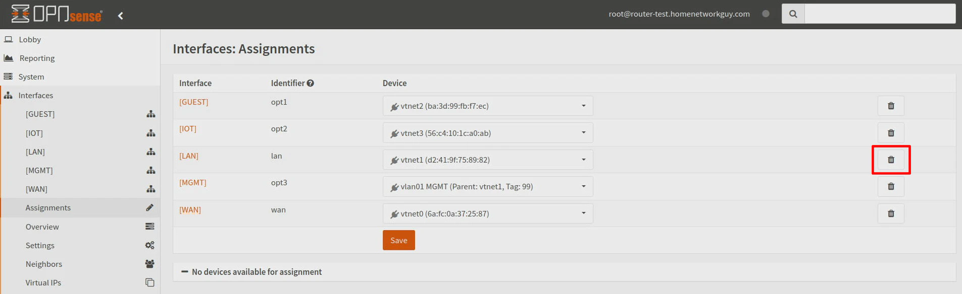
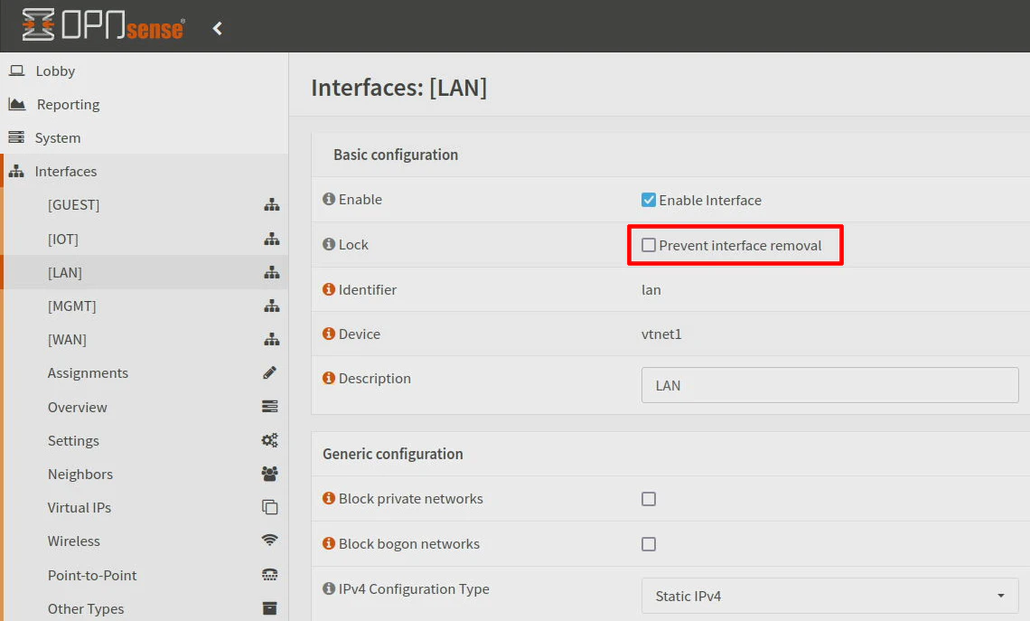
If you do not see the trash icon, make sure you have “Prevent interface removal” unchecked on the “Interfaces > [LAN]” page.
Warning
Make sure you are connected to the MGMT network before removing the LAN interface! Also verify you have connectivity to everything that should be on the MGMT network since you will lose access to anything that is currently on the LAN interface.