How to Configure OPNsense for a Directly Connected PC or Server

Photo by TooMuchCoffeeMan from Pixabay
Table of Contents
One of the most common ways to set up a home network with OPNsense is to use the following configuration: Internet > modem > OPNsense > network switch(es) > end devices/wireless access points.
Many network appliances will have more than 2 ports/interfaces. You may use the extra ports to attach network switches or other devices you may have on your network including PCs, laptops, game consoles, media servers/players, and wireless access points. This may be a convenient option for you based on the location of your OPNsense box.
One important thing to note when using the extra interfaces: they are treated separately by default. They do not function like a network switch. If you want to make the interfaces function like a network switch, it is possible to bridge the interfaces together, but generally that is not recommended since it is done in software rather than in hardware which could bottleneck performance. This how-to will focus on configuring the interface for a device which will be isolated from the rest of the network. Firewall rules may be used if you want to allow access to the device from other internal networks. You may use this approach if you wish to isolate a device without creating a separate VLAN a single device.
Note: If you connect a network switch to the extra port instead of a single device, you can use this same approach to isolate multiple devices on its own network. You are essentially creating a separate physical network rather than using VLANs. If you only have unmanaged switches, using separate physical networks allow you to segregate network traffic without needing to use VLANs, but you will need to use a separate switch for each interface if you wish to have more than one device on each network. There is less flexibility in this approach because you have to make sure devices are plugged into the appropriate network switch. If your switches are not centralized in your house, you will have to run Ethernet cable(s) to the proper switch which may not be convenient.
Connect Device to the Extra OPNsense Interface
For this example, I am assuming the following wired connections as pictured below. The OPT1 interface will be used for a PC in this example:
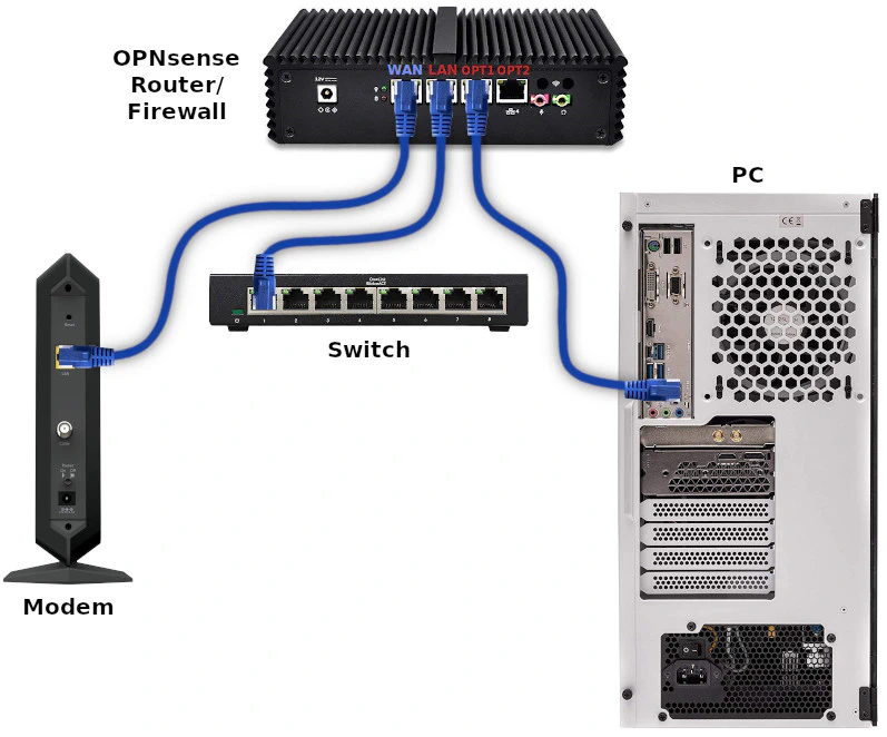
Some network appliances label the Ethernet ports as WAN, LAN, OPT1, OPT2, etc. while others have them labeled 1 to 4. However, I have discovered that the order of the interfaces recognized by OPNsense may differ from the labels on the mini-PC appliance.
Create Network Interface
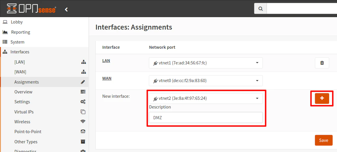
To create a new interface, go to the “Interfaces > Assignments” page. In the “New interface” section, select the interface which your device is plugged into. The icon to the left of the interface name should be green if your device is plugged into the interface. Note that you will only see the “New Interface” section if you have any unused interfaces. As soon as you assign all of your interfaces, that section will be no longer be displayed.
In this example, I am using “DMZ” and the name of the interface since for illustration purposes will be putting the PC on its own isolated DMZ network. Click the “+” button to add the interface.
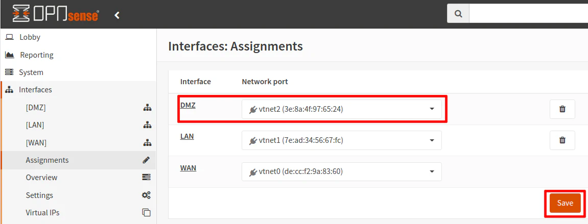
Once the interface is added, you will see it in the interface assignment list. Click the “Save” button to persist the changes. The interface should now be displayed in the left navigation menu.
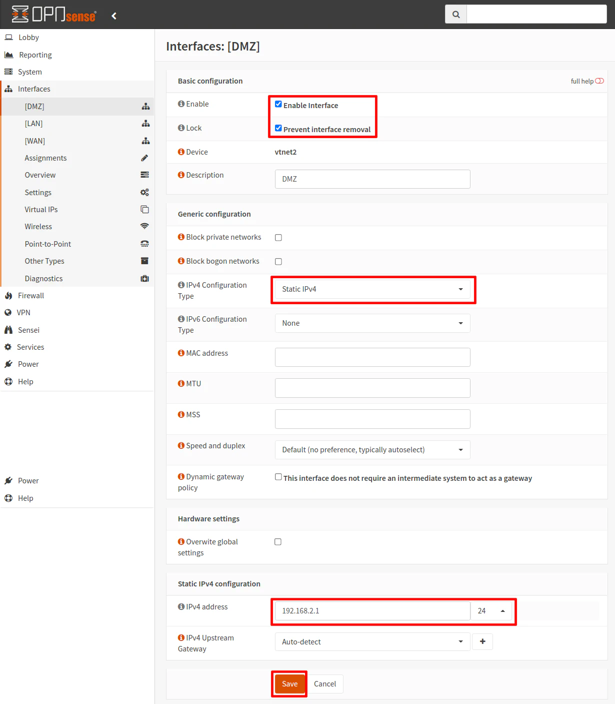
Click on the “[DMZ]” interface page. Click “Enabled Interface” and “Prevent interface removal”. The “Prevent interface removal” keeps you from accidentally removing the interface from the “Interface Assignments” page (the trash icon is removed). This may be helpful when you know an interface is permanent/critical and you do not want to be able to delete it like other interfaces which you may have set up on a more temporary basis (perhaps for a temporary work at home situation).
In the “IPv4 Configuration Type” select “Static IPv4”. You will see a “Static IPv4 configuration” be shown at the bottom of the page. Enter the IP address of the interface. Typically “.1” is used for the last octet to indicate an interface/gateway IP address (similar to how many routers are configured to be 192.168.1.1). Make sure you choose a different IP range than your main LAN. If you are using 192.168.1.1 for the LAN, then using something like 192.168.2.1 as shown in the example for the DMZ will be ok. Select /24 as the CIDR network, which indicates a usable IP range of 192.168.2.1-192.168.2.254. Click the “Save” button when you are finished.
If you have experience configuring a new interface besides the default LAN interface, you will recognize that this configuration is no different when you have a switch plugged into the interface rather than a single device. Keep in mind that the new interface essentially acts as its own network (when not bridged to other interface(s)). The interface itself will have its own IP address and the connected device will have its own IP address within the network range you have defined. You might think that by plugging a single device into the interface that only your PC will have an IP address just like when plugging into a switch port. In reality, both the router interface and the PC have an IP address, which is no different than having a switch in between the router and the PC. When you think about both scenarios behaving the same, configuring the interface in OPNsense makes more sense.
Add the Firewall Rules
Once the interface is created, you can add the firewall rules. It is ok if you do this step last but you will not be able to connect to the network or the Internet without adding the appropriate firewall rules since by default newly created interfaces have all network traffic blocked (unlike the LAN which automatically has an “allow all” rule generated when you first installed OPNsense). By creating the rules now, you will know you have the rest of the configuration correct because you will be able to access the Internet and anything else in your network that you allow access.
For this example, the bare minimum rules you will need is to allow access to the DNS service on the router interface/gateway and an “allow Internet” rule which allows access to any network except for your other local networks (to isolate it from the rest of your network(s)).
The first rule is required because DNS will be blocked by the second rule since an alias containing the RFC1918 private address ranges is used to block all access to other internal/local networks.
| Option | Value |
|---|---|
| Action | Pass |
| Interface | DMZ |
| Protocol | TCP/UDP |
| Source | DMZ net |
| Source Port | any |
| Destination | DMZ address |
| Destination Port | 53 |
| Description | Allow access to DNS on gateway |
The second rule is making use of a network alias called “PrivateNetworks” that was created to contain all of the RFC1918 private address ranges: 10.0.0.0/8,172.16.0.0/12,192.168.0.0/16). The rule makes use of the “Destination invert” option which essentially means “not” the addresses contained in the alias. So the rule below is essentially saying “allow access to addresses that are not in the RFC1918 private address ranges”.
| Option | Value |
|---|---|
| Action | Pass |
| Interface | DMZ |
| Protocol | TCP/UDP |
| Source | DMZ net |
| Source Port | any |
| Destination / Invert | checked |
| Destination | PrivateNetworks |
| Destination Port | any |
| Description | Allow access to Internet |
You may add other rules if you want the PC/server to access services/devices on other parts of your network. Those rules should be above the “allow Internet” rule. Otherwise, the “allow Internet” rule will block access because it blocks all internal networks.
Now you must decide if you wish to use a static IP address or a dynamic IP address. If you wish to have a dynamic IP address, follow the instructions in the “Option 1” section and if you wish to have a static IP follow the steps in “Option 2”. “Option 2” describes 2 ways to configure static IP addresses. If you are hosting services on your network, you may want a static IP address unless you plan to always use the hostname of the PC/server (and you would have to make sure your firewall rules use the hostname via an alias rather than using the IP address which does not require an alias).
Option 1 - Dynamic IP Address
If you wish to use a dynamic IP address so your PC can automatically obtain the network addresses it needs to connect to your network and the Internet, you will need to enable the DHCP service.
Enable DHCP
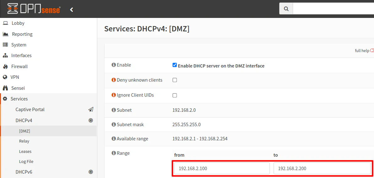
To enable DHCP, go to the “Services > DHCPv4 > [DMZ]” page. If you chose a different name than our example of “DMZ”, click on that name instead. Click the “Enable DHCP server on the DMZ interface” checkbox. Then enter the range of IP address you wish to use. Since you are plugging a single device into this network, it does not need to be a wide range, but it does not hurt anything if you allow a large range. It may not be a bad idea to have a larger range in case you decide later to plug a switch into that port because you will have more address space for more devices.
If you want a static IP address for the PC, you can do it through a DHCP static mapping so you will still need to set up the DHCP service. I prefer to map all static IPs in the router rather than manually configuring each machine with a static IP address since it is nice to have a centralized place to manage static IPs. In this example since there is only one PC you could manually configure the IP address of the PC
Click the “Save” button when you are finished. If you chose this option, you can skip the “Option 2” sections.
Option 2 - Static IP Address
There are 2 ways to set up a static IP address. The first way is to use a static DHCP mapping. I prefer the first way because it allows you to manage all of your static IPs on your network from a centralized location in OPNsense. You do not have to go to each device and manually configure its IP address. However, for this example of one PC on its own interface in OPNsense, you could simply manually configure the PC/server’s IP address since it requires less configuration in OPNsense.
Option 2A - Create a Static DHCP Mapping
For this option, you need to follow the Enable DHCP section above since the DHCP service needs to be active on the router interface. Once it is active, you will have the ability to create a static DHCP mapping.
The easiest way to create a static DHCP mapping is to go to the “Services > DHCPv4 > Leases” page. The “Leases” page shows all of the DHCP leases for all devices on your network. Scroll down to find the device that is on your DMZ network. There should only be one device in the 192.168.2.x range. Click on the “+” button to create a DHCP static mapping.
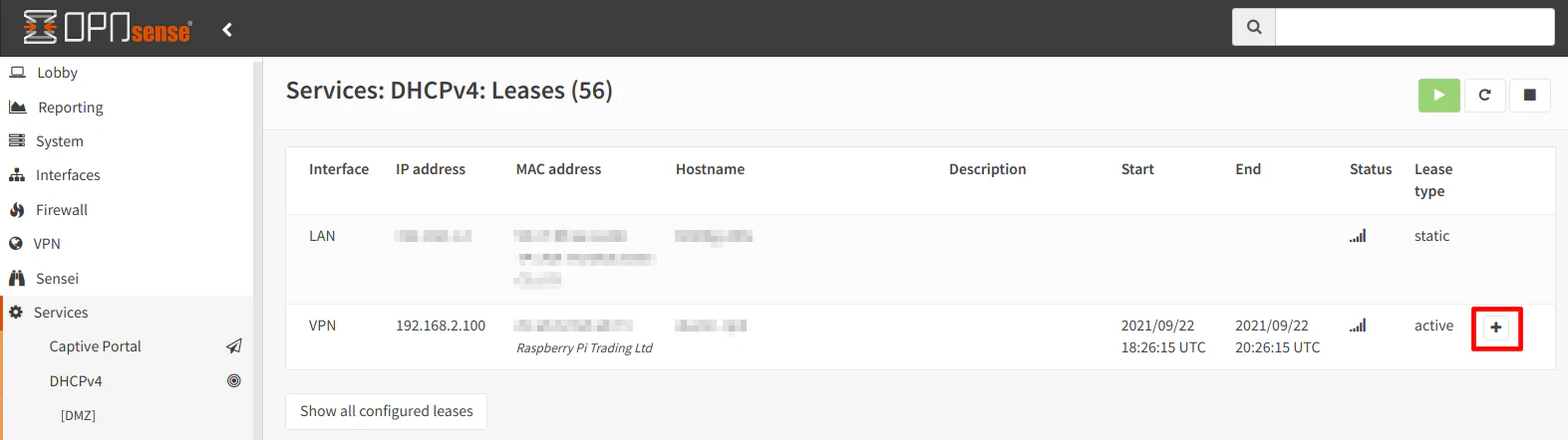
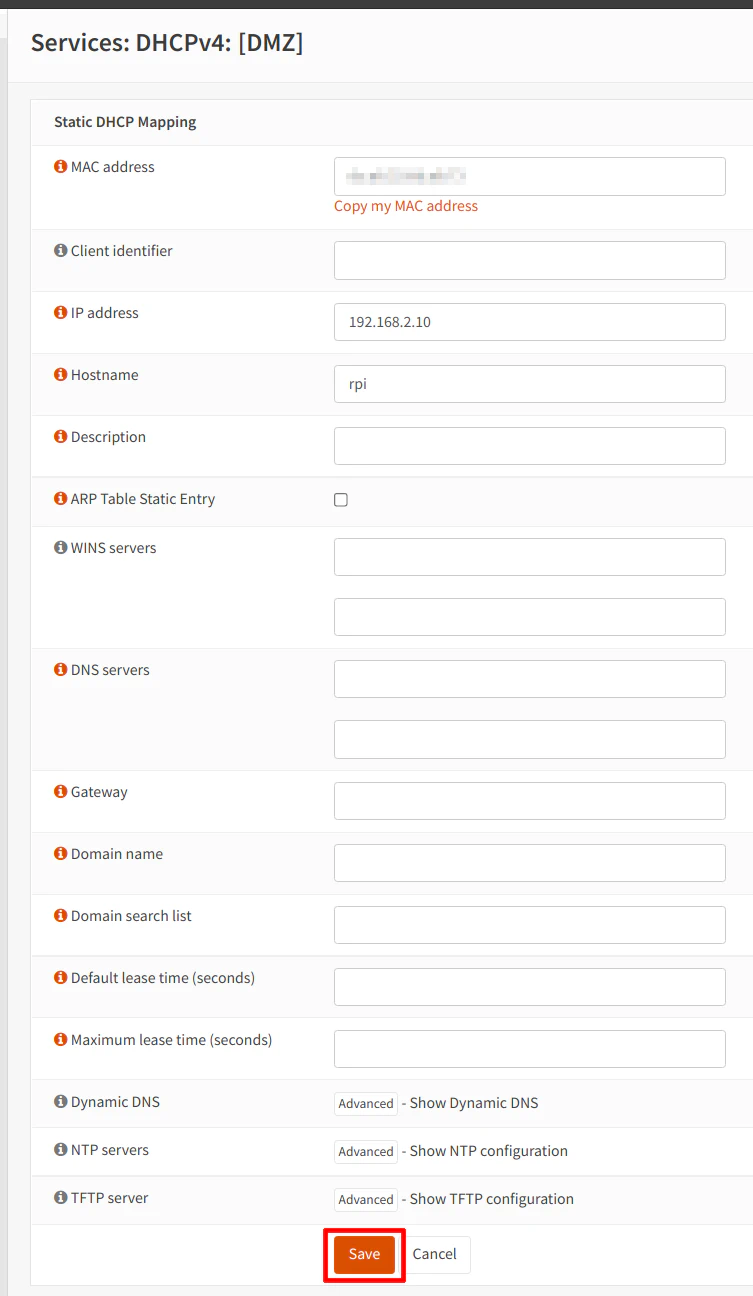
The MAC address should be filled in already. That is the nice thing about adding static mappings from the “Leases” page since it will prefill the MAC address. You can also add a static mapping by going to the “Services > DHCPv4 > [DMZ]” page and scrolling to the bottom of the page. However, it will not prefill the MAC address so you will need to look it up and type it into the box.
Enter an “IP address” of your choice in the box. It must exist within the 192.168.2.2-192.168.2.254 range but outside of the range you specified for dynamic IP addresses. For this example, I have chosen 192.168.2.10. Finally, you will need to add a “Hostname”. Since I am using a Raspberry Pi to test this network configuration, I used “rpi” for the “Hostname”. You can add a “Description” if you like, but it is not required.
Option 2B - Manually Enter Static IP Address on PC/Server
If you are manually configuring the IP address of your PC, you do not need to enable DHCP as you did with “Option 1” or “Option 2A”. You will need to go to the network settings of your Operating System and enter the following information:
| Setting | Value |
|---|---|
| IP Address | 192.168.2.10 (or another address in the 192.168.2.2-192.168.2.254 range) |
| Subnet Mask | 255.255.255.0 |
| Gateway | 192.168.2.1 |
| DNS | 192.168.2.1 |
Conclusion
I hope you found this information helpful even though it may seem like fairly basic information. However, there are some nuances you may not expect when you are new to OPNsense. The fact that the router interface and the PC have separate IP addresses may not necessarily be intuitive to new users. If you imagine the configuration being essentially the same as though you have a network switch in between the router and the devices, configuring the interfaces and firewall rules become more straightforward.