Use Static Routing to Second OPNsense Router with NAT Disabled for a Homelab

Photo by Sritakoset from iStock
Table of Contents
Originally I wanted to write about how to use a second OPNsense router two different ways: with NAT and without NAT. After digging into it further, I decided to write two separate guides to keep each guide to a reasonable length and focused on a specific topic. I am glad that I did because this guide ended up being much more involved than my other guide. Running a second OPNsense router using mostly its default configuration with NAT enabled is by far the easiest way to run a second router in your network. It does not require making any changes to the primary/edge router and allows you to have separate network infrastructure behind the second router.
Another way to configure a second router is to have NAT disabled and making use of static routes on the primary/edge router. I plan to use the same architecture as my other guide to demonstrate the differences. In the scenario described for this guide, OPNsense will be configured as a routing firewall rather than a bridged firewall, which is how OPNsense operates by default. An advantage of a routing firewall is the ability to route data to multiple networks behind the firewall where as a bridged firewall is more like an inline firewall that protects a single interface/network (you could perhaps aggregate several networks behind a single bridge).
Before We Begin
In order to minimize confusion because I am using two OPNsense routers (1 physical, and 1 virtual), the edge/primary router will be using the default user interface color scheme and the secondary router will be using a dark color scheme. I will also state which router is currently being configured in each step. You will need to have a device behind each router to be able to access the web interface. Since I am virtualizing my secondary router, I just put one of my VMs behind the second router so it is easy to configure. If you are using two physical routers, you will need to have at least one physical machine plugged into each router’s LAN.
Network Diagram
For the proposed scenario described in this guide, assume the following basic network diagram. This is the bare minimum you will need to configure both routers so your actual network will likely have many more devices than shown in the diagram. Of course if you are virtualizing the secondary OPNsense router like I am doing, Client 2 could simply be a virtual machine rather than a physically attached system.

The network diagram above is essentially the same as when I wrote about using a second OPNsense router with NAT enabled. However, the approach is different since it will not involve the use of NAT. This guide will explore the differences in great detail.
Note
I would like to mention that you could connect the secondary router to an unused interface on the primary router rather than attaching it directly to the LAN of the primary router. While that is likely a better approach, I wanted to utilize the same physical configuration as my other guide about using NAT but with NAT disabled to demonstrate the differences.
I am writing this guide as a learning exercise so I am not necessarily endorsing this configuration over using a separate physical interface on the primary router. With that said, this scenario may be useful for you to explore if you do not have any extra interfaces available on your primary router. I may revisit using a secondary router on an unused interface in the future since there may be some interesting differences worth discussing.
Install OPNsense on Secondary Router
I am going to assume you already have a primary/edge router deployed on your network and you are wishing to add a secondary router for a separate network. The secondary OPNsense router may be physical or virtual. Ensure that you have at least two physical or virtual interfaces for the WAN and the LAN. Since you are currently reading about this more advanced topic, it is likely you already know the basics of how to install OPNsense (if not, that information should be available online).
As long as you have a client connected to your secondary router, you should be able to modify your configuration later when you follow this guide. One important consideration that I will discuss later when setting up the LAN on the secondary router is choosing a network IP range that is not being used by your primary router. The network(s) behind the secondary router will essentially be treated as additional routable local network(s) when everything is set up properly without NAT, which is why you need to avoid using the same address ranges for your LAN/VLAN networks.
Configure the Secondary Router
I will go through the configuration of the secondary router before the primary router in order to complete the implementation. I have grouped the configuration by type to help keep everything organized as we go forward. Most of the steps outlined below are required for successful implementation, but I have labeled a few steps as optional so you will know when the configuration nice to have but not necessary.
WAN Interface Configuration
The first thing to configure is the WAN interface. The WAN interface will be the means for which all networks behind the secondary router will communicate through. You will need to set up a static IP address for the WAN interface so it can be configured as a gateway and used for static routing.
Set Static IP for WAN Interface
The IP address of the secondary router’s WAN interface should be a static IP address since it will be the gateway address for all networks residing behind that router. Configuring a static IP address can be done in 2 ways:
- DHCP static reservation on the primary router for the secondary router WAN interface
- Static IP configuration on the secondary router WAN interface
The configuration for the first way is simpler on the secondary router because the gateway configuration on the secondary router is automatically created based on the DHCP information provided by the primary router. However, it does require the additional step of creating the static DHCP reservation on the primary router. If you chose the second way, you will manually have to create a gateway on the secondary router, but you do not need to create a static DHCP reservation on the primary router. You could say that both ways require about the same amount of overall configuration, but it depends on where you prefer to manage the configuration. If you prefer to manage most of the configuration on the primary router, use the first option. If you prefer to minimize the amount of configuration on the primary router, then use the second option.
1. DHCP Static Reservation
First thing you need to do if you have not already done so with the default installation of OPNsense is to set your WAN interface of your secondary router to use DHCP. On the “Interfaces > [WAN]” page, set the “IPv4 Configuration Type” to “DHCP” and click “Save”. That is all you need to do to enable DHCP on the WAN interface. You may not have to change anything if you chose “DHCP” for the WAN interface when installing OPNsense on the secondary router.

On the primary router, go to the “Services > DHCPv4 > Leases” page to browse all of the DHCP leases. Find your secondary router’s IP address. In my example, it is 192.168.1.108. You can easily create a new static DHCP lease from the “Leases” page. I prefer to create static leases from this page rather than creating the lease from the interface’s page because it prefills the MAC address. You do not have to copy/paste or type the MAC address.
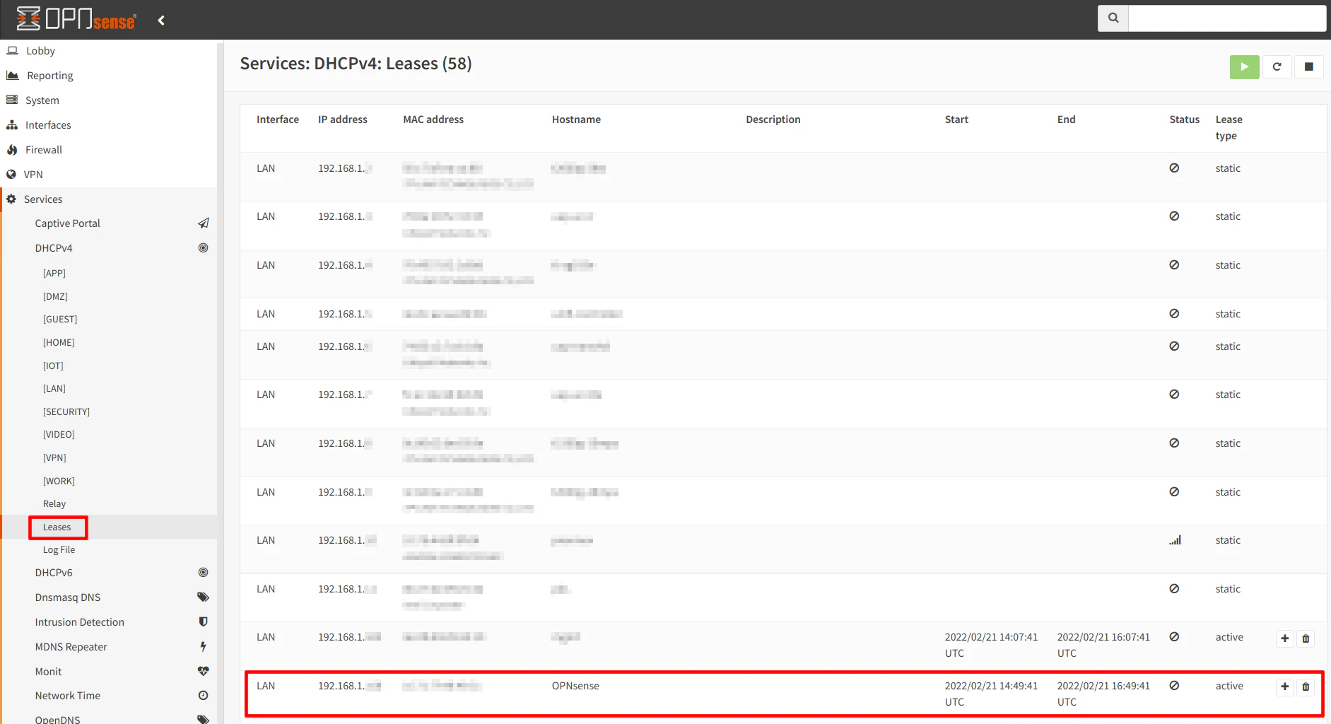
The “MAC address” should be filled in. Enter the “IP address” and “Hostname” for the secondary OPNsense box. This hostname will override the name you configured on your secondary router. You may want to use the same hostname so that it is not confusing when referring the hostname from both networks. You may optionally add a “Description” as well. Click “Save” when you are done and click “Apply Change” at the top of the page to make the changes take effect.

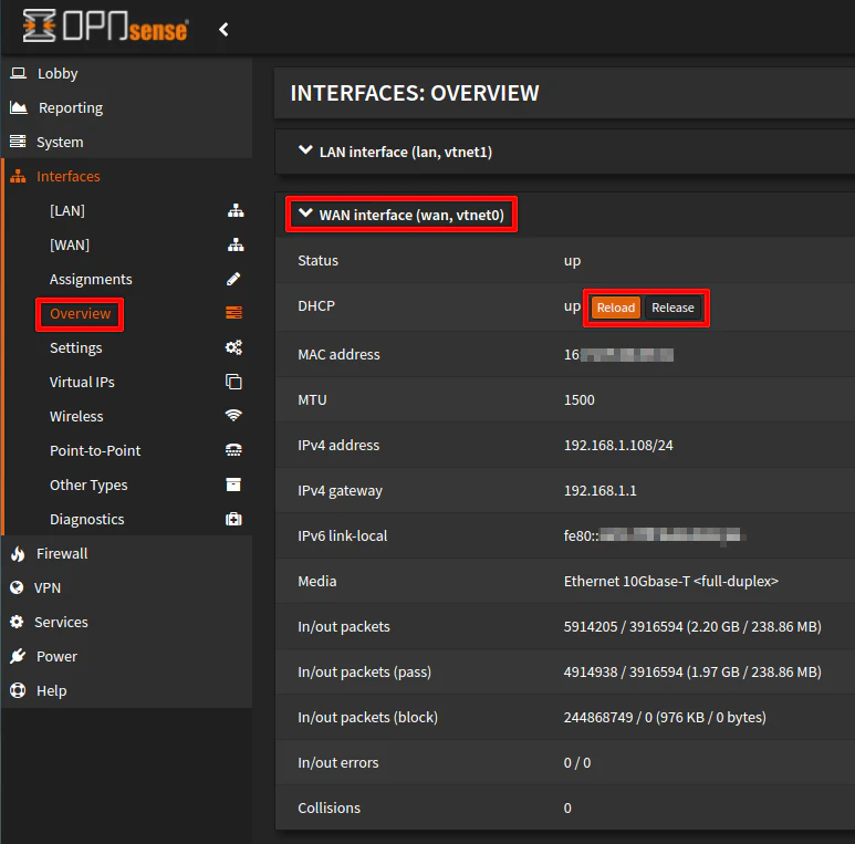
If you want your new IP address assigned to take effect immediately, you may need to release/reload the IP address on the WAN of the secondary router. You may do that by visiting the “Interfaces > Overview” page under the “WAN interface” section.
You make skip the next section if you choose to use DHCP for the WAN interface.
2. Static IP Configuration
If you are not using DHCP as described in the previous section, you must manually configure a static IP address for the WAN as described in this section.
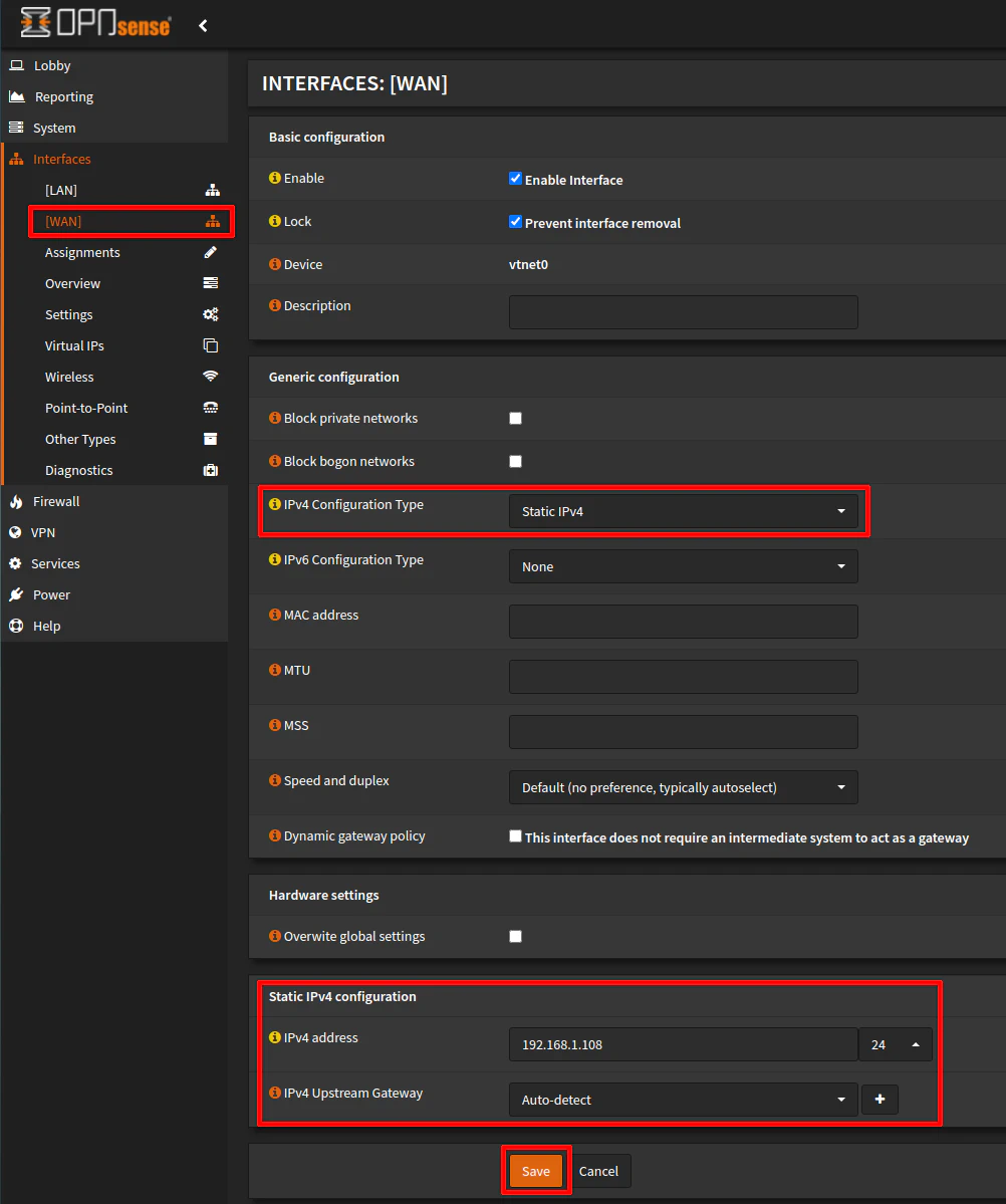
To configure a static IP address for the WAN interface, go to the “Interfaces > [WAN]” page and select “Static IPv4” for the “IPv4 Configuration Type” option. That will open up a new section at the bottom of the page to enter the IP address information. You will need to enter an IP address in the range of the network you are connected to on the primary router and is not in the DHCP range you have assigned for that network to avoid potential IP address conflicts. In this example, I am using 192.168.1.108. The CIDR should be set to /24 (the dropdown does not include the slash). If you are using a larger network address range, you can select a different value than /24, but for most home networks using /24 is plenty since it allows up to 254 devices per network. The “IPv4 Upstream Gateway” can be left at “Auto-detect” since there is only going to be one gateway address for the WAN.
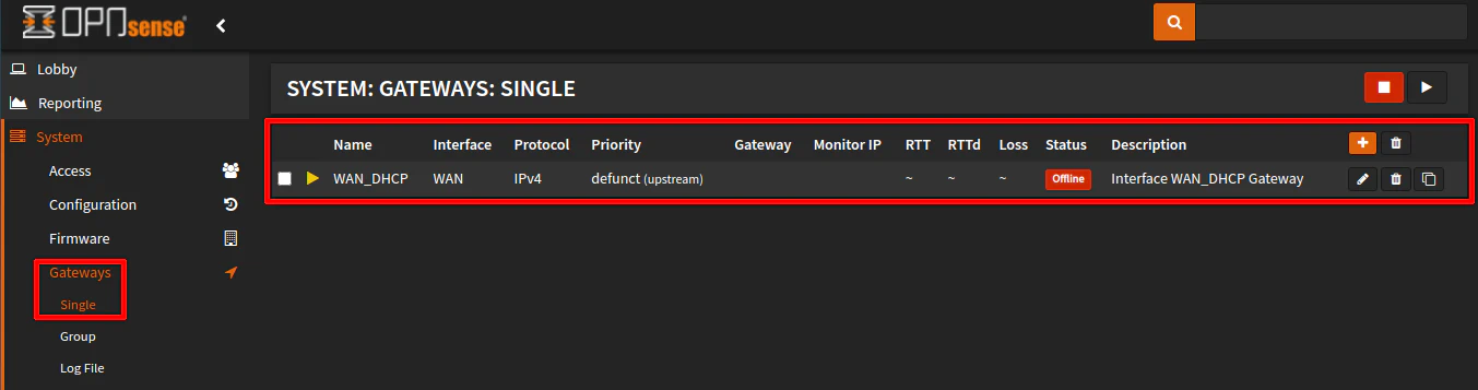
Since the IP address is manually assigned, a gateway must be created manually in order for all of the routing to function properly. On the “System > Gateways > Single” page, you may notice that you have a lingering DHCP generated gateway if you are switching from the default DHCP configuration to a static IP for the WAN interface. If you see a “defunct” DHCP gateway, you may delete it using the trash icon before proceeding to add a new gateway.
Note
Do not worry – it is safe to delete the unused DHCP gateway in this case since it is not needed. If you decide to switch back to DHCP, the gateway will regenerate once again.
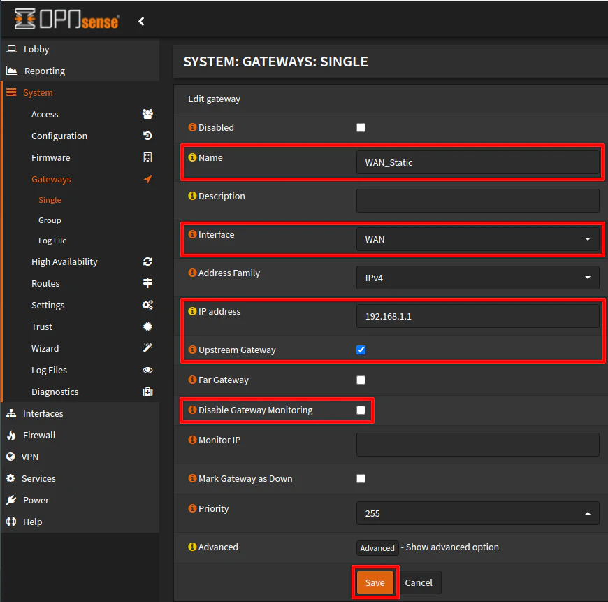
Click on the “+” icon to create a new gateway. Enter a descriptive “Name” for the interface. Choose “WAN” as the “Interface” since the WAN will use this as a gateway.
Enter the “IP address” of the gateway. This will be the IP address of the network interface of the primary router. Since I am connected to the LAN of the primary router with an interface address of 192.168.1.1, that is what I am using in this example. However, if you are connected to another LAN/VLAN with an interface address of 192.168.20.1, you would use that as the gateway address. It is the same address as other devices that reside on that same primary router’s network. For clients on the primary router, the WAN of the secondary router will simply be another network address that exists on that network.
You may check the “Upstream Gateway” option since it is an upstream gateway rather than a downstream gateway to other parts of your network. Also you can uncheck “Disable Gateway Monitoring” if you wish to have the status of the gateway be displayed on the “Dashboard” of the web interface. Note that this requires you to allow the WAN interface of the secondary router to ping the gateway address on the primary router. Click “Save” when you are finished.
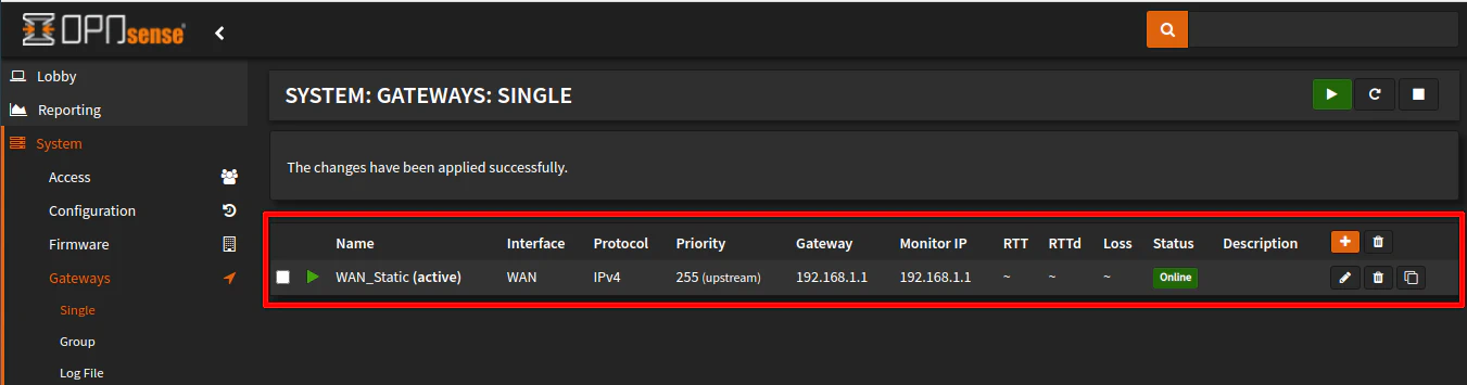
Once you have saved the gateway, you should see it listed and be shown as “Online”. You may not immediately see the round trip times until you refresh the page after a few seconds as it gathers those statistics by pinging the gateway. If you have disabled ping (ICMP), you may not see this information and the gateway may show as offline even though it is not actually offline.
Allow Private Networks on WAN Interface
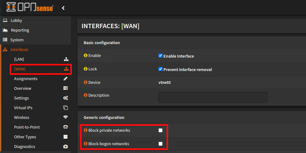
While you are still on the WAN interface configuration page, make sure you uncheck both “Block private networks” and “Block bogon networks”. You may have noticed I have already done that in the screenshots of the previous DHCP/static IP configuration steps, but I wanted to separate this step to call attention to the importance of unchecking these options because you will run into trouble later if you skip this step.
Traffic originating from private IP addresses and bogons are blocked from the WAN interface by default as a security measure when the router is on the edge of your network since it should only be receiving traffic from public IP addresses. The secondary router WAN interface will reside on your local network so private IP addresses need to be allowed for incoming private IP WAN traffic.
LAN Interface Configuration on Secondary Router
The LAN interface should already be configured from your initial installation and as long as your IP address ranges for the network do not overlap or conflict with any networks on the primary router, you should be good for your LAN configuration. You may enable DHCP and allocate the IP address ranges for DHCP as you see fit. In my example, I will be using 172.16.1.1/24 for the LAN network behind the secondary router since I am using 192.168.x.x addresses for my primary router networks. Using the 172.16.x.x addresses will make it obvious they are behind the secondary router.
DNS Configuration
DNS is an essential service that needs configured for networks. I must admit that I tried different ways to configure DNS when implementing the scenario described in this guide and not all of the ways were successful. A question I had was, ‘Is it better to use Unbound DNS on both routers or only on the primary router?’ In my mind, I thought it might be a good idea for the secondary router to have its own Unbound DNS service configured so DNS can be managed for all networks behind the secondary router. The primary router could then be used as the upstream DNS server. However as I explain below after exploring a number of options, I found it made sense to simply use the Unbound DNS of the primary router. In the end, I personally prefer having a single DNS service to manage especially since it was already configured and available for use in my network. I do not need to worry about possibility of troubleshooting two different DNS services when I experience issues. Although I will demonstrate using the primary router’s DNS service, you may wish to experiment with DNS in other ways on your secondary router if you prefer that option.
Disable Unbound DNS
As I have mentioned, I tried running Unbound DNS on the secondary router. However, this seemed to cause at least one odd issue. DNS lookups would not resolve all of the hostnames on the primary router networks. It would only return IPv6 addresses for a hostname and/or only hosts that I have configured on the “Unbound DNS Overrides” page of the primary router. At one point, I even had Unbound set up in forwarding mode to send all DNS requests to the primary router (but if you doing that, you might as well directly use the Unbound DNS of the primary router because in forwarding mode, the secondary router DNS will not resolve any hostnames since it simply forwards DNS lookups upstream). It is quite possible I had a misconfiguration because I was trying different ways to configure DNS so you may not necessarily have the same experience.
After some time I realized that configuring the secondary router to use the Unbound DNS of the primary router may be more convenient because it simplifies the configuration of the secondary router. Also, hostnames that are recognized via DHCP mappings, static mappings, and DNS overrides on the primary router are recognized by networks behind both routers. Centralized management of DNS for all networks on the primary and secondary router is convenient.
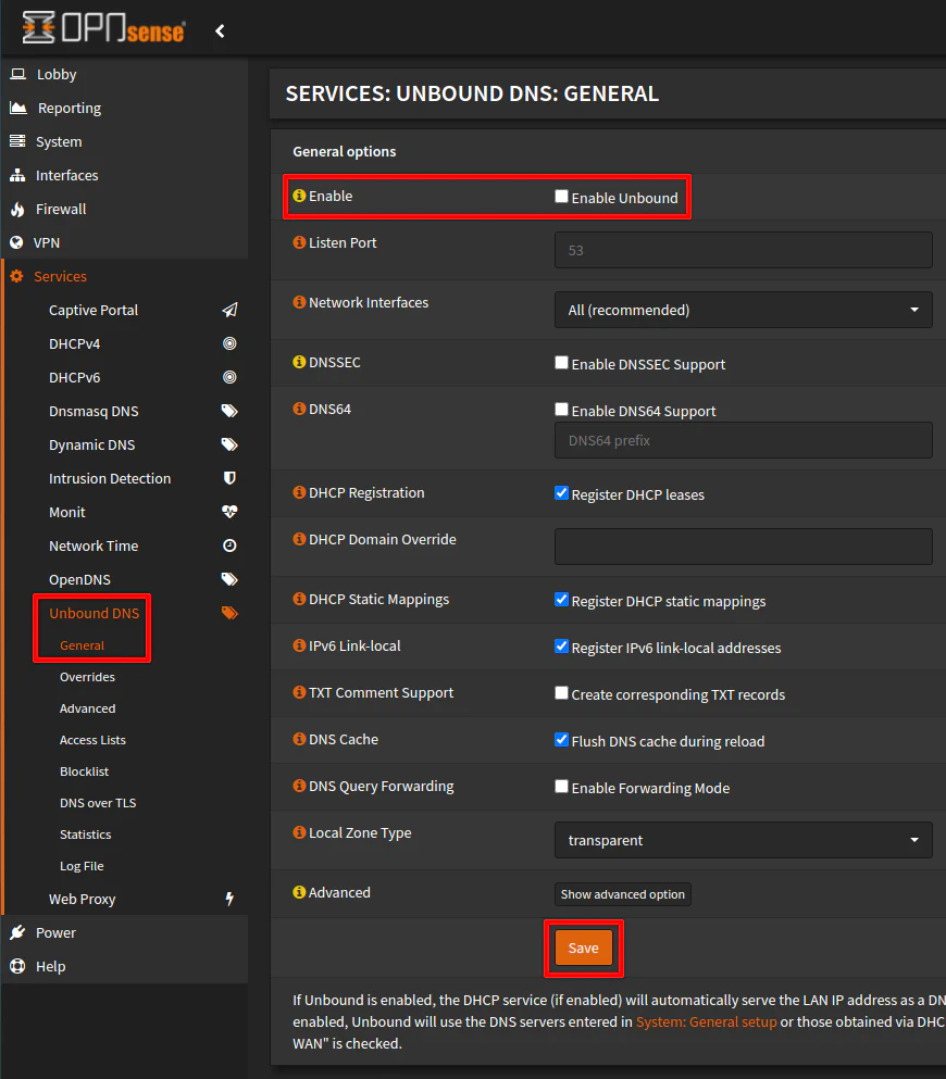
To disable Unbound DNS, uncheck the “Enable Unbound” box on the “Services > Unbound DNS > General” page. Click “Save” to disable Unbound DNS.
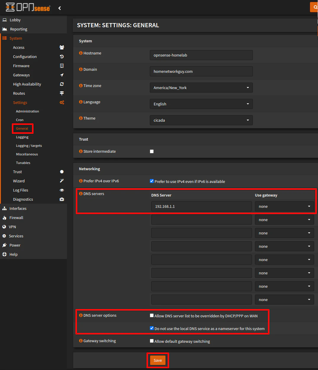
Configure the DNS Server in the System Settings
Now that Unbound DNS is disabled, you need to configure the DNS server in the system settings so the networks behind the secondary router can resolve host/domain names. On the “System > Settings > General” page, enter the DNS server in the “DNS servers” section of the page. In my example, the DNS server for the LAN network of the primary router is 192.168.1.1.
For the “DNS server options”, you may wish to uncheck “Allow DNS server list to be overridden by DHCP/PPP on WAN” just to make sure it does not try to use another DNS server automatically (but I doubt it matters since the WAN is not external facing so there should be no concern of it using the ISP DNS servers via DHCP). Since we are not using the Unbound DNS on the secondary router, you can check the option “Do not use the local DNS service as a nameserver for this system”. You probably do not really need to do it if Unbound is disabled, but it probably does not hurt to do since we want to ensure all DNS lookups to go through the DNS server of the primary router. Click “Save” when you are finished.
Firewall Configuration for Secondary Router
A guide such as this would not be complete without the firewall configuration. Some of the configuration options and rules must be implemented while others are optional based on what traffic you want to allow on your network.
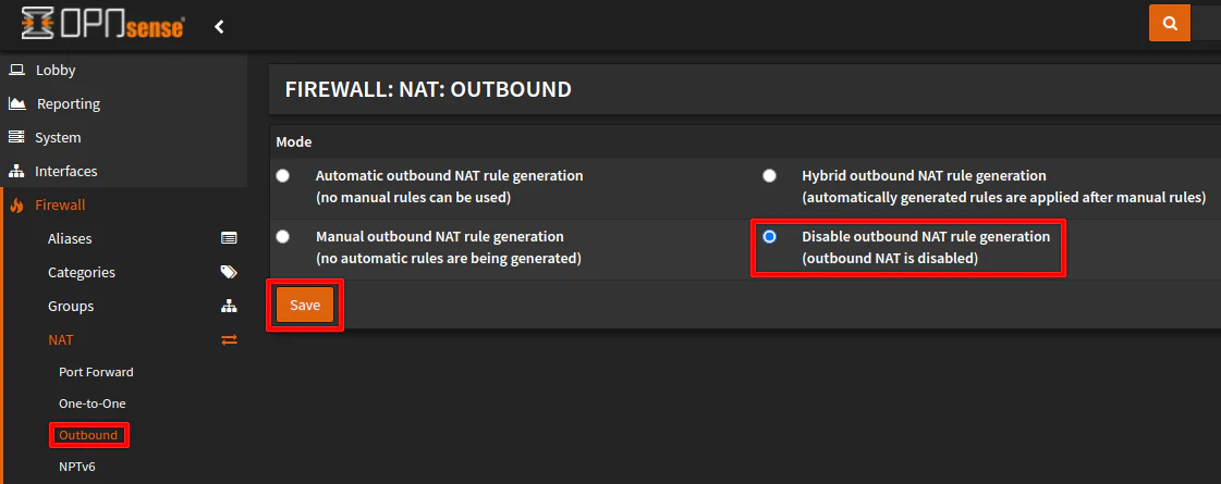
Disable Outbound NAT Rules
The scenario discussed in this guide is all about adding a secondary router to your network without the use of NAT and this is the step which is necessary to disable NAT. Visit the “Firewall > NAT > Outbound” page and click the “Disable outbound NAT rule generation (outbound NAT is disabled)” radio button. Click “Save” to apply the changes.
WAN Rules
For the WAN interface on the secondary router there are two rules I will focus on. The first rule is necessary if you want devices on the primary router to access anything behind the secondary router. The second rule allows you to monitor the gateway status of the secondary router from the primary router’s web interface. Either rule may be optional if you do not have a need to implement them.
1. Allow Access to Secondary Router LAN from Primary Router LAN
If you wish to access devices/services behind the secondary router from the primary router, you need to implement a rule that allows traffic entering the WAN interface to access the LAN or other networks behind your secondary router. For traffic coming from the LAN of the primary router (which is the network where the secondary router is connected) to any network behind the secondary router, the WAN rule below will be sufficient to allow that traffic.
Go to the “Firewall > Rules > WAN” page and click on the “+” button. The “Interface” should be set to “WAN” by default when creating a new rule on the WAN interface so many of the default values do not need to be changed unless you want to be more granular. The source can be the LAN addresses of the primary router which is 192.168.1.0/24 in my example. Any traffic coming from the LAN of the primary router will be allowed to the LAN of the secondary router. You can make the source more specific if you only want a specific device such as 192.168.1.100 to access the LAN network on the secondary router. For the “Destination” in this example, I chose the LAN net. This LAN is the LAN of the secondary router and not the primary router. Like with the “Source”, you can chose a more specific destination such as 172.16.1.100 rather than the LAN net which is 172.16.1.0/24 for the example scenario.
| Option | Value |
|---|---|
| Action | Pass |
| Interface | WAN |
| TCP/IP Version | IPv4 (or IPv4+IPv6) |
| Protocol | any |
| Source | Single host or Network: 192.168.1.0/24 (or alias containing both IPv4/IPv6 addresses) |
| Destination | LAN net (or other network(s)) |
| Description | Allow traffic from the primary router through the WAN interface |
If the traffic is coming from another network on the primary router where the secondary router is not connected, you will need an additional firewall rule for that primary router network to allow access to the secondary router network. For instance, suppose there is a VLAN 20 with the IP addresses of 192.168.20.0/24 on the primary router and you want VLAN 20 to access the LAN on the secondary router, you need to implement the following rule on the primary router:
| Option | Value |
|---|---|
| Action | Pass |
| Interface | VLAN20 (on primary router) |
| TCP/IP Version | IPv4 (or IPv4+IPv6) |
| Protocol | any |
| Source | VLAN20 net (which is 192.168.20.0/24) |
| Destination | 172.16.1.0/24 (which is the addresses of the LAN on the secondary router) |
| Description | Allow traffic from VLAN20 to the secondary router LAN |
2. Allow ICMP on WAN Interface for Gateway Monitoring
Another WAN rule which you may want to include but is optional is a rule to allow ICMP on the WAN interface. This rule allows you to monitor the gateway status of the secondary router’s WAN interface from the primary router. Without this rule, your gateway will show as offline even though it is not actually offline. If you do not want any other device pinging the WAN interface from the primary router, you could limit the source to the IP address of your primary router (such as 192.168.1.1 in my example).
| Option | Value |
|---|---|
| Action | Pass |
| Interface | WAN |
| TCP/IP Version | IPv4 (or IPv4+IPv6) |
| Protocol | ICMP |
| ICMP Type | any |
| Source | Single host or Network: 192.168.1.1/32 |
| Destination | WAN address |
| Description | Allow ICMP on the WAN interface for gateway monitoring |
LAN Rules for Secondary Router
If you essentially started with a default installation of OPNsense on your secondary router, you will likely have default allow rules for IPv4 and IPv6 (if you enabled IPv6). I recommend you change these rules unless you want the devices on your secondary router LAN network to have full access to all networks on your primary network. Most users would likely want to lock things down more than that. If you are using your primary network as a DMZ, perhaps having an allow all rule might be ok but you can still lock down access further even to the DMZ network by using specific IPs/ports to all of the devices/service in which you need access. That is typically a better approach than simply allowing full access to another network on your local network. It sort of defeats the purpose of segregating your network.
In the examples below, I am going to assume you are removing the default allow rules and implementing the more restrictive firewall rules below. Click “Apply” after removing/add all of the firewall rules for the changes to take effect.
1. Allow access to DNS Server on Primary Router
The first firewall rule that needs to be implemented is to allow access to the DNS server of the primary router network, which in my example is 192.168.1.1. This rule is necessary since you are not using the Unbound DNS of the secondary router.
The “Source” should be “LAN net” for the 172.16.1.0/24 network on the secondary router. The “Destination” as mentioned already should be 192.168.1.1/32. The “Destination port range” should be the standard DNS port 53. If you are using IPv6, you could either create a corresponding rule using the IPv6 of the DNS server on the primary router or you can create an alias which has both the IPv4 and IPv6 addresses and combine them into a single rule by selecting “IPv4+IPv6” as the “TCP/IP Version” using the alias for the “Destination”.
| Option | Value |
|---|---|
| Action | Pass |
| Interface | LAN |
| TCP/IP Version | IPv4 |
| Protocol | TCP/UDP |
| Source | LAN net |
| Destination | Single host or Network: 192.168.1.1/32 |
| Destination port range | DNS (53) |
| Description | Allow access to DNS server |
Tip
If you have more than one network behind the secondary router, you may want to create either a floating rule or a firewall group so you could allow all of the interfaces to access the DNS server with a single rule instead of duplicating this rule in every network.
2. Allow Access to the OPNsense Web Interface
A rule to allow access to the OPNsense web interface is necessary because rule #3 below is going to be used to block access to all private network addresses to isolate all local networks (it is easier to block all private IP addresses than to allow only specific networks because you do not have to maintain a list of networks each time to you add or remove a network). Rule #3 will block access to anything on the LAN interface (172.16.1.1) including access to the OPNsense web interface since it is a private IP address so this rule is critical to implement.
For the rule below, use “LAN net” as the “Source” and “LAN address” as the “Destination”. You may wonder why this rule is necessary since the traffic is technically on the same 172.16.1.x network. Services that are hosted on the interfaces, however, can be blocked by the firewall since the traffic is entering into the network interface. That is why for DNS, etc. you need a rule to allow access to the interface address if you are blocking the all private IP addresses.
| Option | Value |
|---|---|
| Action | Pass |
| Interface | LAN |
| TCP/IP Version | IPv4 (or IPv4+IPv6) |
| Protocol | TCP |
| Source | LAN net (172.16.1.0/24) |
| Destination | LAN address (172.16.1.1/32) |
| Destination port range | HTTPS (443) |
| Description | Allow access to the OPNsense web UI |
3. Block Access to All Other Local Network and Allow Access to the Internet
To finish up the minimum set of firewall rules for the LAN, access needs to be blocked for all local networks but allowed for the Internet. The rule below will ensure your LAN network behind your secondary router cannot access other parts of your network unless other rules are added above this rule. You will notice the destination port is set to “any” but you could be more restrictive and only allow HTTPS traffic. You need to have a good understanding of the ports used by all services that you use before you start restricting ports. Otherwise, you may get help desk tickets from your family or friends.
It is also important to note that the “Destination / Invert” option is checked because this is what causes the private networks to be blocked and allow access to all other networks (which is the networks on the public Internet). Essentially this rule is saying “allow access to any network that is not a local private network”, which is all publicly accessible networks on the Internet.
| Option | Value |
|---|---|
| Action | Pass |
| Interface | LAN |
| TCP/IP Version | IPv4 (or IPv4+IPv6) |
| Protocol | TCP |
| Source | LAN net |
| Destination / Invert | checked (very important!) |
| Destination | PrivateNetworks (an alias containing 10.0.0.0/8,172.16.0.0/12,192.168.0.0/16, and your IPv6 networks if applicable) |
| Destination port range | any |
| Description | Block access to private networks and allow access to the Internet |
If you need to allow access to devices/services on other networks on either the primary or secondary router, you will need to create additional rules above this rule. Because everyone hosts different services on their network and have different needs, you will need to add those rules yourself. You may want to look at my firewall rule cheat sheet for example rules you can create if you are new to writing firewall rules.
Tip
You will need to create additional rules on the primary router if you wish to access a device/network other than the LAN of the primary network from the secondary router LAN. An example will be shown in the LAN firewall rules section of the primary router.
Configure the Primary Router
Next up is the primary router configuration. Because you are tweaking your primary router, I recommend creating a backup of the configuration or the virtual machine of your primary router due to the potential risk of messing up your main network(s). When I learning how to properly configure everything in this how-to, I somehow ended up causing some odd connectivity issue where connections would randomly drop momentarily on a regular basis. I was tinkering a good bit while I was learning, but I may have been a little too careless with making changes. After restoring the configuration of my primary router from the backup file, I tried again and all was well.
With that said, I hope you can learn from my mistakes! Of course, I cannot guarantee everything will work perfectly in this guide for you since everyone has their own way of setting up their network(s), and it is possible configurations suggested in this guide will conflict with other settings in your network. If you are starting with a more basic network or from scratch, you are less likely to experience issues assuming you have the basic infrastructure connected/installed correctly before following this guide.
Create Gateway to Secondary Router WAN Interface
Similar to how the secondary router needs a gateway to the primary router, the primary router needs a gateway created for the secondary router. The purpose of gateways is for routers to know where to forward packets upstream and downstream to other routers on the network. The discovery of gateways of the routers can be either dynamic or static. I am describing how to do it statically which is often the recommended way if you have only a few routers on your network since the configuration is easier than setting up dynamic protocols.
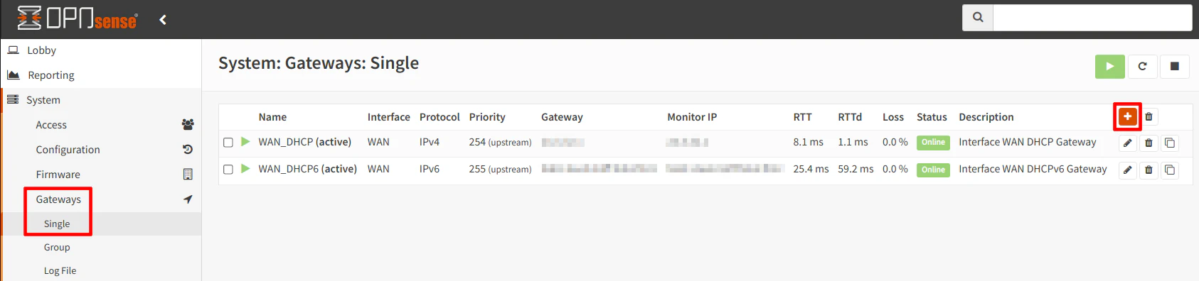
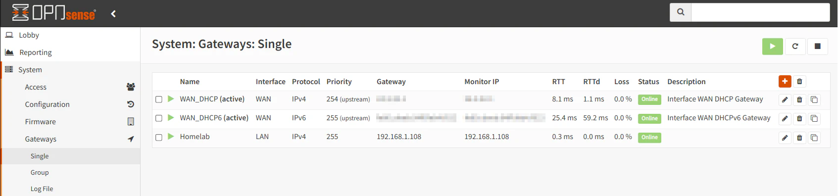
On the “System > Gateways > Single” page of your primary router, you will see your existing gateways. For most users, this will be DHCP and if you have IPv6 enabled, you will see two gateways as shown in the screenshot below. Click the “+” button to add a new gateway for the secondary router that is attached to the LAN of the primary router.
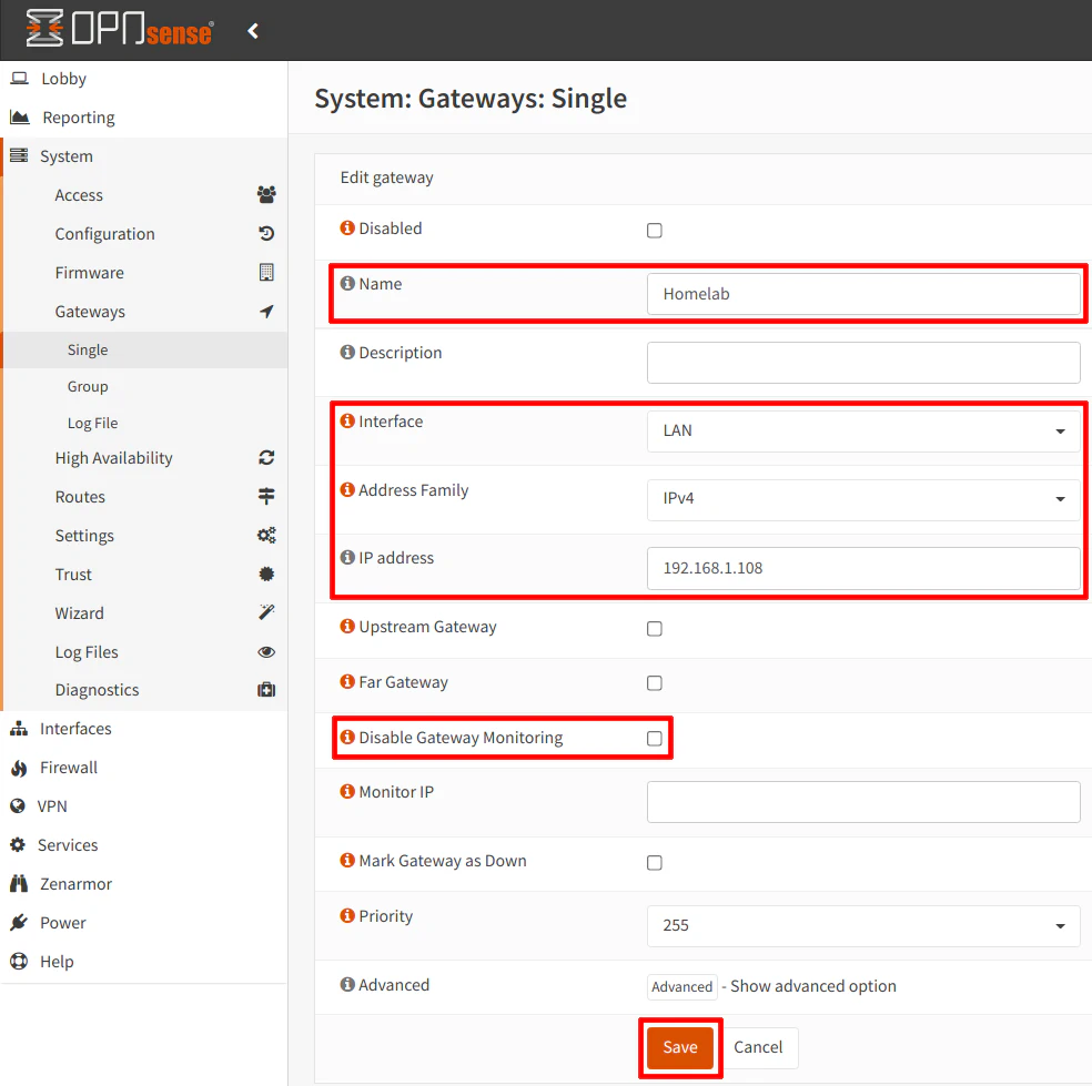
Provide a “Name” that will be shown on the gateway page. I am using “Homelab” in my example since that is one possible reason you may want to have a secondary router with its own separate network(s). Select the “Interface” where your secondary router is connected. For this scenario, I chose the “LAN” interface. To keep things simple and familiar to many home users, I am using “IPv4” as the “Address Family”, but if you wish to use IPv6 you may choose that instead. If you want to use both IPv4 and IPv6 you will need to create 2 separate gateways. Enter the “IP address” of the secondary router’s WAN interface. As stated earlier in this guide, the WAN interface of the secondary router is using 192.168.1.108.
Optionally, you can choose to uncheck “Disable Gateway Monitoring” if you want to be able to see if the secondary router’s WAN interface is online from the primary router’s “Gateways” page. This may be useful for troubleshooting purposes. In order for this to work, you will need to allow ICMP (ping) on the WAN interface of the secondary router which I have described earlier. Click “Save” when you are finished entering the information.
You should be able to see the new gateway on the “Gateways” page. It should show as online if you decide to do the gateway monitoring.
Create Static Route for the LAN on the Secondary Router
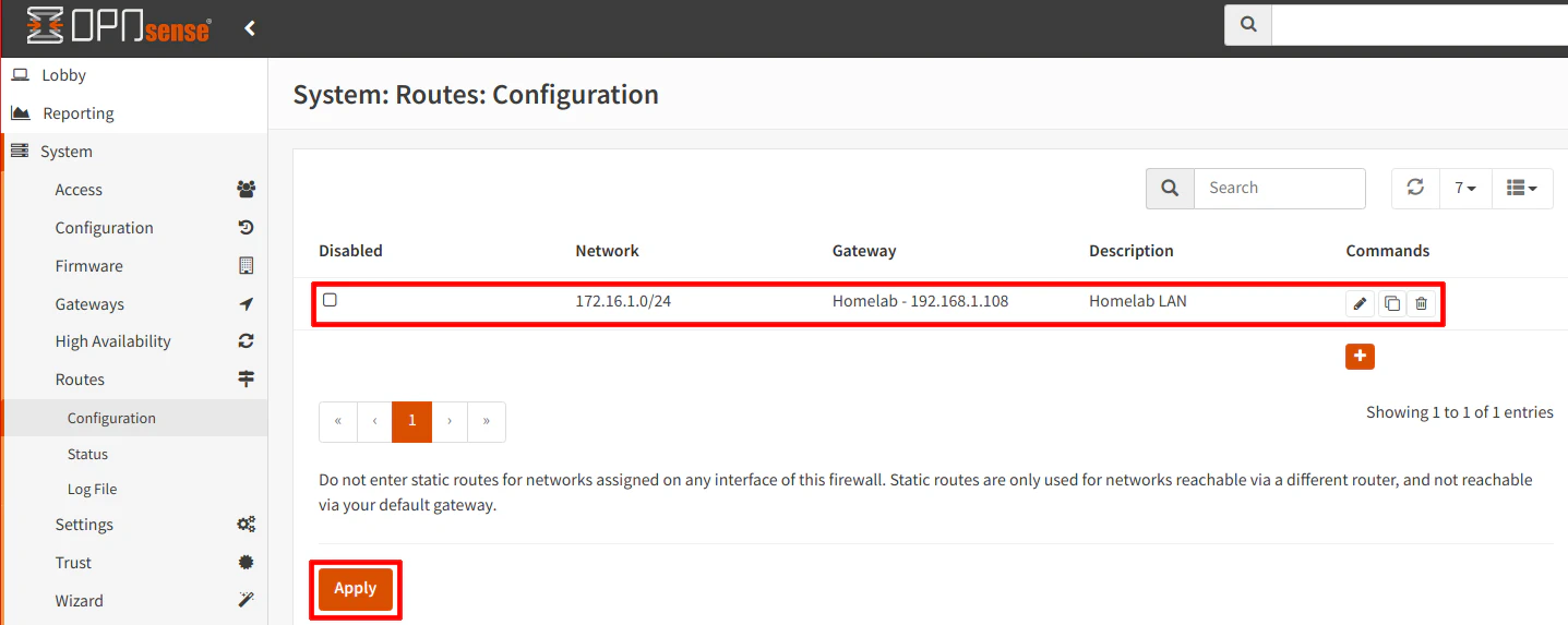
With the gateway you created in the previous step, you will need to use it for the static route you are going to create in this step. On the “System > Routes > Configuration” page, click the “+” button to create a new static route. For the “Network Address”, I am using 172.16.1.0/24 in my example, which is the addresses used for the LAN of the secondary router. Next, select the “Homelab” gateway that you created earlier for the secondary router. Finally, enter a “Description” if you desire, and click the “Save” button.
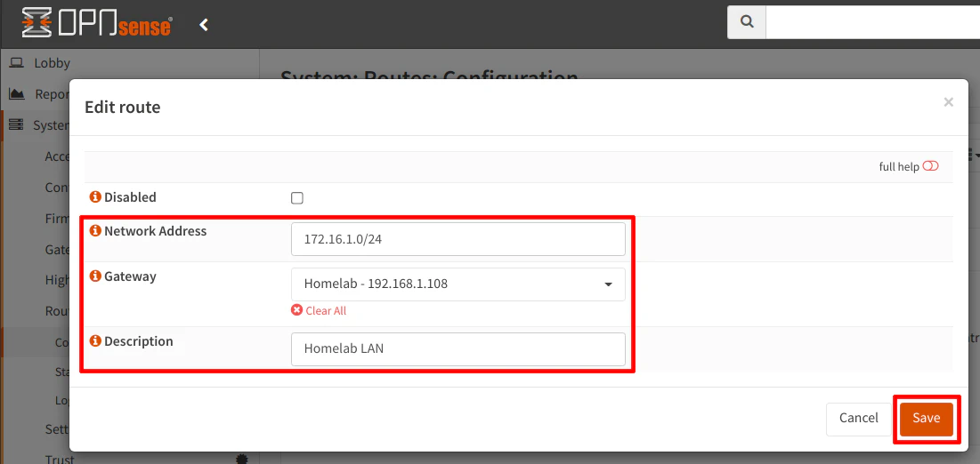
The static route should be displayed in the list of routes. Click the “Apply” button to finish up the static route configuration.
Firewall Configuration for the Primary Router
Now onto the firewall configuration for the primary router that need to be implemented in order for the example scenario to function properly.
Static Route Filtering
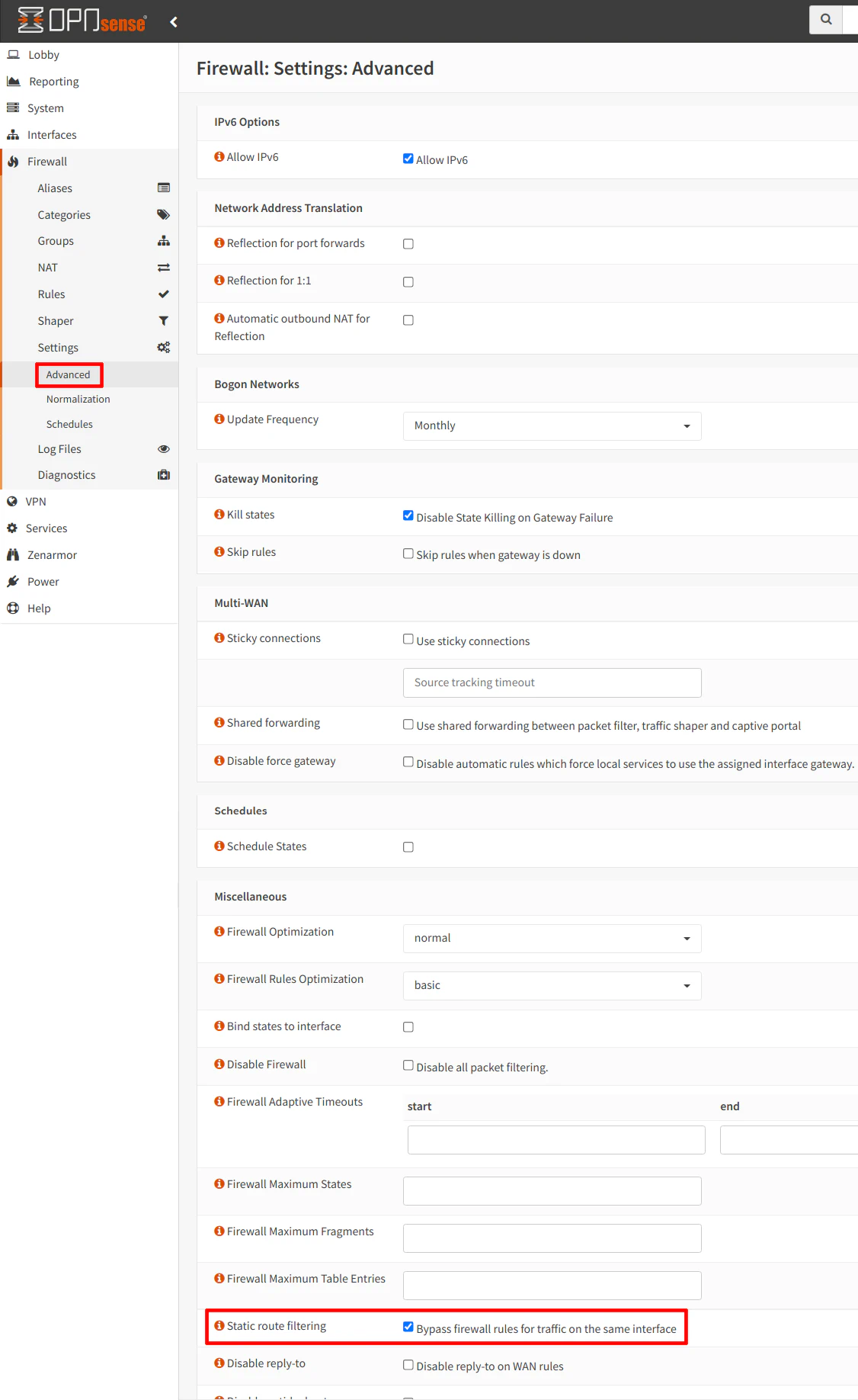
On the “Firewall > Settings > Advanced” page, you will need to check the box “Bypass firewall rules for traffic on the same interface” for the “Static route filtering” option. This option is necessary for asymmetric routing. I must admit I do not quite understand it as fully as I would like. The general idea is that the network path taken by the outgoing traffic is different than the path of the corresponding return traffic.
In our example, the return traffic of traffic originating from the LAN of the secondary router has trouble getting back to the secondary router LAN since it will be coming back through the LAN interface of the primary router before it reaches the LAN of the secondary router. So traffic that leaves the secondary router’s LAN cannot receive any data packets that come back as a response to the original request. When testing this option, it seems it only affected traffic going out to the Internet from the secondary router’s LAN. Traffic going to any network on the primary router from the secondary router LAN seemed to get the proper response back. I am assuming the static route configuration along with the corresponding firewall rules allows the traffic to route back to the secondary router properly when the traffic does not leave and enter the WAN of the primary router. Please keep in mind I am speculating a bit on a few thoughts based on my limited understanding of asymmetric routing so I recommend doing more research on this topic if you are curious about it.
One thing I am certain about is that this option is critical to enable because when I disable it, I can no longer access any external websites, etc. from the secondary router LAN.
Note
This option may not be necessary if you connect the secondary router to a separate, unused interface on the primary router as I mentioned in the Network Diagram section. That is a slightly different scenario which I may explore in the future since that is potentially a better approach that may have some interesting differences in configuration worth discussing.
Outbound NAT Rule for the Primary Router
‘Outbound NAT rule’ in a guide about not using NAT? Yes, you read that correctly. You may wonder why we need to create an outbound NAT rule when this guide is focused on NAT being disabled. Earlier in this guide, NAT was only disabled for the secondary router but NAT is still enabled for the primary router (I am assuming most home users are using NAT on the primary router connected to the Internet since that is the most common scenario).
Even though the network(s) behind the secondary router are now routable among all of your local network(s), traffic from the secondary router networks will not be able to reach the Internet without the outbound NAT rule since the local network addresses are not being translated to the external WAN IP address of your home network due to NAT on the secondary router being disabled. If NAT was enabled on the secondary router, addresses would be translated to the WAN IP of the secondary router and if that traffic leaves the primary router, it will then be translated to the WAN IP of the primary router which allows traffic to flow properly in a double NAT scenario. However, since the network addresses on the secondary router are not translated via NAT, a rule must be created on the primary router to translate the traffic coming from the secondary router.
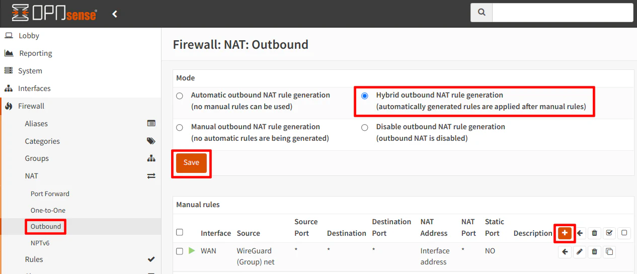
Navigate to the “Firewall > NAT > Outbound” page. To add custom outbound NAT rules, you will need to switch to hybrid mode. On my primary router, I am already using hybrid mode since I have an outbound rule set up for my WireGuard VPN server. Hybrid mode is nice because it leaves the automatically generated outbound NAT rules in place but also allows you to manually create additional rules. Otherwise, you would have had to recreate all of the default outbound NAT rules for all of your internal networks so that they can access the Internet. Click “Save” after selecting “Hybrid outbound NAT rule generation”. Then click on the “+” icon to add a new outbound NAT rule.
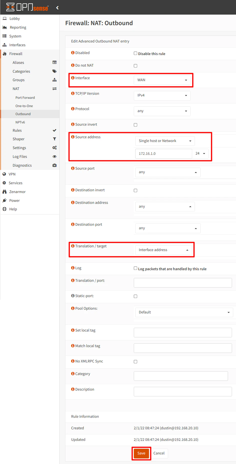
When adding a new rule, you can likely leave almost all of the settings at the default, but I highlighted the most important settings in the screenshot. The “Interface” needs to be “WAN”. The “Source address” needs to be “Single host or Network” with the network address of 172.16.1.0/24 which is the LAN on the secondary router. You could create an alias if you have more than one network behind the secondary router so you do not need to create multiple outbound NAT rules. Finally, the “Translation / target” should be set to “Interface address” so the secondary router’s LAN addresses get translated to the WAN IP of the primary router when traffic is leaving your home network out to the Internet.
LAN Rules for Primary Router
There are two example rules that I would like to discuss for the LAN interface of the primary router. The first rule must be created if you wish to access any devices/services on any LANs/VLANs on the primary router and the Internet from the secondary router.
1. Allow Access from Secondary Router LAN to Primary Router Networks and the Internet
I mentioned above in the secondary router LAN rules section that if you add rules to the LAN of the secondary router to allow access to anything on the primary router network(s) except for the LAN on the primary network you will need to create an additional rule on the primary router. This is due to the fact that the traffic for 172.16.1.x is passing through the LAN interface of the primary router on the 192.168.1.x network. Therefore, a rule needs to be created to allow 172.16.1.x to the desired network(s)/device(s) from the primary router LAN.
Because a corresponding rule must exist on the secondary router’s LAN interface, it may be more convenient (especially if you have multiple networks behind the secondary router) to create a less restrictive as shown in the example below since you may forget to update this rule when creating new rules for the secondary router network(s). That could lead to wasted time troubleshooting firewall rule issues. I realize some may prefer to make everything very tight, but keep in mind that you will need to update the rule below as you create more rules for the secondary router unless the rule you create below covers the additional rules. If you prefer to lock things down as tight as possible, you should change the source and destination accordingly.
For this example, on the “Firewall > Rules > LAN” page, add a rule that has “LAN” as the “Interface” and the secondary router LAN address range of 172.16.1.0/24 as the “Source”. Normally you would use “LAN net” or a specific IP within the LAN as the “Source”. However, the 172.16.1.x network originates on the primary router LAN because that is where the secondary router is attached. For the “Destination” and “Destination port range”, if you choose “any” for both, this rule will support any firewall rules you create on the secondary router LAN interface where you need to access devices on your internal network(s) and the Internet. Remember this rule by itself does not allow access to all internal/external networks on the primary router since additional rules need created on the secondary router LAN interface. It does, however, allow access to the primary router LAN since it is on the same network that the secondary router is connected.
| Option | Value |
|---|---|
| Action | Pass |
| Interface | LAN (of primary router) |
| TCP/IP Version | IPv4 (or IPv4+IPv6) |
| Protocol | TCP/UDP |
| Source | Single host or Network: 172.16.1.0/24 |
| Destination | any |
| Destination port range | any |
| Description | Allow access from secondary router LAN to primary router networks and the Internet |
If you want to lock down the rule above to only allow access to the Internet for the secondary router LAN and block access to all networks on the primary router, you may check the “Destination / Invert” box and use the private network address ranges as the destination. As with the other rule above, you will need to have a rule on the secondary router LAN to allow access to the Internet and block all private networks (but it will need to be below the rule to allow DNS). There are other variations of this rule you can use if you wish to lock things down more or have other needs.
| Option | Value |
|---|---|
| Action | Pass |
| Interface | LAN (of primary router) |
| TCP/IP Version | IPv4 (or IPv4+IPv6) |
| Protocol | TCP/UDP |
| Source | Single host or Network: 172.16.1.0/24 |
| Destination / Invert | checked (very important!) |
| Destination | PrivateNetworks (an alias containing 10.0.0.0/8,172.16.0.0/12,192.168.0.0/16, and your IPv6 networks if applicable) |
| Destination port range | any |
| Description | Allow access from secondary router LAN to the Internet and block access to everything else |
2. Allow Access to All Devices on the Secondary Router LAN
The second type of rule I want to show is to allow access from the primary router to any network/device on the secondary network. This rule is pretty straightforward and is similar to other rules you may be using to access other parts of your network. Since your actual devices/services you need to access can vary, you will have to decide what rules you will need but you may use the example below as a starting point.
Use the “LAN net” (or another network) as the “Source” and enter 172.16.1.0/24 as the “Destination” to allow access to all devices on the secondary router LAN. You can, of course, use specific IP addresses and port numbers for the “Destination” to lock things down tighter.
| Option | Value |
|---|---|
| Action | Pass |
| Interface | LAN (of primary router or any other interface) |
| TCP/IP Version | IPv4 (or IPv4+IPv6) |
| Protocol | TCP/UDP |
| Source | LAN net (or any other corresponding interface) |
| Destination | 172.16.1.0/24 |
| Destination port range | any |
| Description | Allow access to all devices on the secondary router LAN |
Create an Alias on the Primary Router for the Secondary Router Network Address (Optional)
If you have several rules on the primary router to allow access to the networks/devices on the secondary router, you may want to create an alias so that it is easier to reference those networks in your rules. By default, OPNsense creates aliases for “LAN net”, etc. but you can create your own aliases to mimic this behavior so you do not have to type 172.16.1.0/24. They could be named like “HomelabNet” (you cannot have spaces in custom alias names).
For more information on how to create various aliases, please refer to my guide on aliases.
Conclusion
As you may have gathered based on the length of this guide, configuring a second firewall without NAT using static routes is a lot more involved that using a second router that simply uses NAT. However, my hope is that you can see where this type of configuration could be beneficial in standing up one or more networks behind a second router/firewall. You gain the ability to have multiple networks behind the second router without the limitation of port forwarding from the WAN interface to devices behind the second router – no double NAT issues! If you have more than one app/service you are trying to access on the same port behind the second router, you will be able to do so using the configuration discussed in this guide because you will have the option to simply write firewall rules to allow access to all of the apps/services on devices behind the second router. If you were using a secondary router with NAT enabled, you would not be able to port forward the same port to multiple servers on your network (I suppose you may be able to work around that for web servers using a reverse proxy, but that is another service you may not wish to configure for your network).
As I have mentioned in this guide, there may be a few simplifications and minor differences in configuration if you choose to connect your secondary router to an unused interface of the primary router, but I wanted to explore how to configure a second OPNsense without NAT using the same network design as my other guide which used NAT. I believe this was an interesting learning exercise which may be beneficial to those who do not have any extra interfaces on their primary router (such as a 2-port network appliance).
Using the concepts in this guide, you could use your primary network as a DMZ to host public apps/services and the secondary network(s) as part of your private home network as a potential extra layer of protection. Or you could use the primary network(s) as local private network(s) and use the secondary network(s) for homelab usage where you can build, break, and teardown without impacting other parts of the network. If using the second router as part of a homelab, you can run a completely independent physical or virtual hardware stack. That is one great thing about building your own network – you can build it to suit your needs and there are a number of ways you may achieve it!