Beginner's Guide to Set Up a Home Network Using OPNsense

Photo by Rasi Bhadramani from iStock
Table of Contents
My most popular guide at the time of this writing is how to set up a full network using OPNsense. In that guide, I combine many of the concepts I have written about over the years. The guide has been generally well received but as more new users started following that guide, some confusion has arisen about the concept of LAGGs and when it is appropriate to use them.
Link aggregation (LAGG) is useful for providing redundancy if one or more interfaces fail but also can be helpful in increasing bandwidth of multiple simultaneous streams of data. For 1 Gbps interfaces, they are much easier to saturate on a regular basis than higher speed interfaces. Normal day to day usage will likely not saturate 1 Gbps. Of course, downloading and copying data between two computers can easily saturate 1 Gbps. LAGGs may be helpful for performance on slower links like 1 Gbps only if you have more than 1 device on your network saturating 1 Gbps at the same time.
Many users choose to implement a LAGG without knowing for certain if they actually need it. Perhaps I did not spell that out clearly enough in my original guide. I recommend implementing a LAGG on your OPNsense box only if you know for certain you have bottlenecks for network traffic going across your various internal networks and you know that your OPNsense box is capable of handling the increased capacity. LAGGs can be used for redundancy/high availability purposes but to be honest, in the past I used the same cheap mini-PC appliance for OPNsense for over 5 years without any hardware failures so it is not something which occurs frequently in my experience.
As 2.5/10G interfaces become more affordable, there is less need to utilize LAGGs on your network (except maybe for redundancy/high availability purposes). Therefore, I recommend taking advantage of those higher speed interfaces on your network to alleviate any potential bottlenecks. I personally no longer have any LAGGs configured since I have introduced 10 Gbps interfaces on my network.
The Intention of the Original Guide
The intention of the original guide was to simply demonstrate several concepts in one comprehensive guide so that new users did not have to piece together a bunch of guides on specific topics hoping to make everything work together. The original guide was aimed more toward users who had a good understanding of networking but wanted to go beyond a basic home network to help improve security, privacy, etc. Therefore, the original guide included more configuration than what many new users would likely need to implement to simply get started.
For instance, new users may not need or want to create 5 VLANs on their networks. I included 5 VLANs as examples of the different types of VLANs that users may wish to implement on their networks so they could pick and choose which ones are appropriate to use for their home networks. In addition, LAGGs (link aggregations) are completely unnecessary unless the purpose of utilizing LAGGs is fully understood and there is good reason to implement them.
I have always advocated for new users to start with the basic configuration before working towards a more complex configuration. By taking one step at a time slowly, accomplishing goals becomes much easier and attainable. Implementing a more complex network all at once may be an overwhelming and frustrating experience if issues arise. Understanding the fundamentals first before moving forward is a great approach to learning and reaching goals.
Although the primary focus of this website is generally aimed toward intermediate to more advanced home network users, I try to also make the content approachable to new users the best I can. However, in order to keep guides on topic and constrained, I do have to assume that some basic level of understanding of networking has to exist when creating guides.
With that said, I have decided to create this alternate version of setting up a full network which has a greatly simplified network architecture to help beginners get started with using OPNsense to build out a full network.
I will be using a 4 port mini-PC such as the Protectli VP2420 (affiliate link) , a managed network switch such as the TP-Link T1500G-10MPS (affiliate link) , and a wireless access point capable of supporting VLANs such as the Grandstream GWN7660 (affiliate link) .
To follow along, you will need similar equipment. As I mentioned in the original guide, the way VLANs are configured for the network switch and wireless access point may vary depending on which vendor you are using so it is not possible for me to demonstrate how to do the configuration for every type of device that exists. However, once you understand the concepts of VLANs, you should be able to implement it on your specific hardware.
Note
Disclaimer: As stated in the original guide: This is yet another network architecture example you may use as a reference. I am not claiming that this architecture is the best way to implement your home network. You know your needs the best and you should be able to choose or omit portions of this guide.
Network Architecture
The example network will assume the following architecture:
- The connection from the ISP will be connected directly to the WAN interface of the OPNsense system
- The LAN interface will be connected to a smart/managed network switch and will also contain a single VLAN for untrusted devices (a router on a stick configuration)
- A wireless access point will be connected to the network switch to provide wireless for the networks
- Other devices will be connected to the network switch and will reside either in the trusted LAN or the untrusted VLAN
- The network will only use IPv4 to keep configuration simple (see the IPv6 configuration guide or the original full network guide if you wish to implement IPv6)
To keep the configuration minimal, only a single physical network interface will be used for the LAN and the VLAN which will contain all of the untrusted devices.
Even though you could utilize two different physical interfaces to accomplish the separation between trusted and untrusted devices, I want to introduce the concept of creating a single VLAN because this is a good foundational concept to learn in order to build out a more complex network. Once you understand how to create one VLAN, you will be able to create additional VLANs in the future for other purposes as you build out your network.
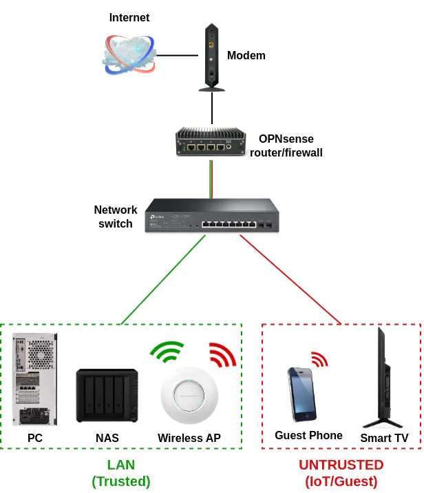
Logical Network Diagram
Below is a logical network diagram that will be implemented in by this guide:
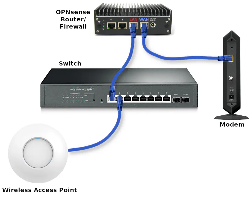
Physical Diagram of Network Infrastructure
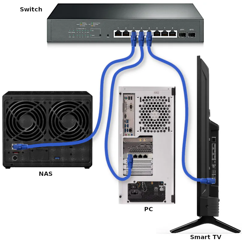
Refer to the image below for the physical connections of the network infrastructure that I will be using.
To keep the physical network infrastructure image less cluttered, the image below only shows the basic network infrastructure described in my example and not the various devices connected to the network (see also the physical diagram of connected devices).
TL;DR Overview
Because this guide will be longer than my usual content, below is an outline of what will be done to complete the full network example I am discussing:
- Install OPNsense
- Configure OPNsense
- Configure network switch
- Configure wireless access point
The full setup may seem daunting, but I am including a lot of configuration information with brief descriptions in an effort to show all of the necessary or recommended values to build a fully functioning network with OPNsense.
Let us get started with installing OPNsense!
Install OPNsense
The first step you need to do is install OPNsense on your hardware. I am using a Protectli VP2420 in my network example, but you can use any hardware compatible with OPNsense.
Go to the OPNsense download page. Choose the “vga” installer so you can install it on a USB drive. Use a program such as Etcher to flash the drive with the image you just downloaded (you do not even have to extract the image if you are using Etcher).
To keep this guide shorter, I will not include screenshots in this step like I did with my installation guide.
- Do not press any key when prompted for the configuration importer
- Press any key for manual interface assignment (I prefer to manually configure than using the automatic process)
- Press “Enter” to skip the LAGG configuration
- Press “Enter” to skip creating VLANs (will do this later in the web interface)
- Enter
igc0for the WAN interface name (for the Protectli VP2420 – your interface name may be different such asigb0) - Enter
igc1for the LAN interface name (for the Protectli VP2420 – your interface name may be different such asigb1) - When prompted for an optional interface name, press “Enter” to skip configuration (will do this later)
- Press “y” and “Enter” to continue
- At the login prompt, enter the username
installerand the passwordopnsenseto continue with the installation - Press “Enter” to continue with the default keymap (if you are using the US keyboard, otherwise select the appropriate option)
- Select the “Install (ZFS)” option to use the ZFS filesystem
- Select the disk where you want to install it (you should be able to tell the difference between the USB and internal hard drive based on the name and size)
- Select “Yes” to continue with the recommended swap partition size of 8 GB
- Select “Yes” to continue to destroy the current contents of the disk
- Select “Change root password” now so you do not forget (you will use this to log into the web interface or console)
- Enter the password twice
- Select “Complete Install” to finish installing OPNsense
When it is finished, it will reboot and you should see a login screen which lists the IP addresses of all your interfaces.
Configure OPNsense
Before configuring OPNsense, make sure you have your PC, laptop, or other device you wish to use to configure OPNsense plugged into the LAN interface. In our example, that would be the second interface from the right side of the box.
The LAN interface will be used to configure OPNsense, but once the network switch has been configured, you will plug your network switch into the LAN interface so you can connect more than one device to your network. You will still be able to manage OPNsense if you are connected to any interface on the switch which is set to the default VLAN 1.
For the OPNsense configuration, you will need to login to the default https://192.168.1.1 URL. You could use the default opnsense.local hostname, but if you decide to change the default host/domain name later when configuring OPNsense, you will have to switch to the new hostname in your browser to continue the configuration. If you use the IP address instead, you will not be interrupted due to an OPNsense host/domain name change.
Configuration Wizard
You will be presented with the configuration wizard when you first log into OPNsense. The configuration wizard is completely optional. In this guide, I will skip using the configuration wizard so that you will know where all of the configuration options are located in case you want to make changes in the future. Click on the OPNsense logo in the upper left hand corner of the page to skip the wizard.
System Configuration
The system settings is a good place to start with configuring OPNsense. I will cover the most common settings you will like want to change, but of course if your needs are different, you can deviate from this guide.
Settings: General
On the “System > Settings > General” page, you can customize a few network-wide settings such as the domain name and DNS settings, which can be confusing since there are a few places where you can configure various DNS options. Of course, these settings are free for you to change to your own personal preferences. For instance, I do not expect you to use homenetworkguy.com as your domain name for your network!
| Option | Value |
|---|---|
| Hostname | router (or choose your own hostname) |
| Domain | homenetworkguy.com (choose your own domain name) |
| Time zone | America/New_York (choose your own time zone) |
| DNS servers | Leave blank |
| DNS server options | Check “Allow DNS server list to be overridden by DHCP/PPP on WAN” |
Settings: Administration
The “System > Settings > Administration” page contains useful configuration for how you wish to access OPNsense (web, SSH, and console):
Web GUI:
| Option | Value |
|---|---|
| Protocol | HTTPS (should be the default value) |
| HTTP Strict Transport Security | Check “Enable HTTP Strict Transport Security” |
| TCP port | Leave as 443 |
| HTTP Redirect | Leave unchecked |
| DNS Rebind Check | Leave unchecked for security (may interfere with certain name resolutions) |
| HTTP Compression | High (if you have a reasonably fast system or “Low” otherwise) |
| Listen Interfaces | LAN (only listen on the LAN interface to limit access to web GUI from the VLANs) |
You may configure the SSH/console access but for simplicity for beginners, I am not including those extra settings since most beginners will likely be accessing OPNsense via the web interface.
Settings: Miscellaneous
The “System > Settings > Miscellaneous” page has a few options you may want to tweak such as the CPU type for the thermal sensors widget on the “Dashboard”. There are some periodic backup options, power savings options, and memory/swap options.
| Option | Value |
|---|---|
| Thermal Sensors Hardware | Intel Core CPU (unless you have AMD hardware) |
| Periodic RRD Backup | 24 hours (optional) |
| Periodic DHCP Leases Backup | 24 hours (optional) |
| Periodic NetFlow Backup | 24 hours (optional) |
| Use PowerD | Checked (if you have power saving options enabled in the BIOS) |
| Power Mode | Hiadaptive (to favor performance over power savings) |
If you are using a SSD or a traditional hard disk, you should not need to adjust any of the disk/memory settings at the bottom of the page since those options are more designed for systems where you want to minimize wear on the disk or if disk space is very constrained. Modern SSDs can handle a lot of writes before the disks wear out.
Interface Configuration
Next up is configuring the interfaces. For this simplified guide which does not include LAGG configuration, the only interface you will need to create is a VLAN interface since the WAN and LAN interfaces were created during the initial installation.
Interfaces: Settings
| Option | Value |
|---|---|
| Hardware CRC | Check “Disable hardware checksum offload” (if not already checked) |
| Hardware TSO | Check “Disable hardware TCP segmentation offload” (if not already checked) |
| Hardware LRO | Check “Disable hardware large receive offload” (if not already checked) |
| VLAN Hardware Filtering | Choose the “Disable VLAN Hardware Filtering” option |
I have often seen the recommendation to disable hardware offloading on the network interfaces due to various issues that may be encountered. For most users, it is always best to leave it off unless you have thoroughly tested out these configuration options.
In a home network, hardware offloading (if it works) is likely less impactful than using it on a heavily saturated business or enterprise network unless you regularly saturate your network’s bandwidth.
If you are using IDS/IPS services such as Suricata or Zenarmor, hardware offloading should be disabled since it is incompatible with netmap.
Other Types: VLAN
A VLAN is a virtual network that resides on top of a physical network. VLANs allow you to create multiple virtual networks on physical hardware so that you have the flexibility of separating network traffic (each have their own broadcast domains) without needing to purchase additional hardware for each physical network.
Not only is utilizing VLANs cost effective, but it allows you to make better use of your network resources. Limiting broadcast domains can improve performance on your network if you have a large number of devices especially if they utilize a significant amount of bandwidth. When combining VLANs with firewalls, you can also improve the overall security of your network by limiting access between groups of devices.
In this guide, I am going to create one VLAN for untrusted devices on your network. The original guide provided 5 different VLAN examples but to keep this guide simplified, only a single VLAN will be demonstrated to help you get started with segregating your devices to improve network security.
To create a VLAN in OPNsense, go to the “Interfaces > Other Types > VLAN” page. When creating the VLAN, you will use the LAN interface as the parent interface. As mentioned above, VLANs require a physical interface in which to create logical networks.
| Option | Value |
|---|---|
| Device | Leave empty to automatically generate a name |
| Parent | igc1 (use the LAN interface as the parent) |
| VLAN tag | 10 |
| VLAN priority | You may use the default “Best Effort” or select priorities (not sure how much it impacts actual performance) |
| Description | UNTRUSTED |
Interfaces: Assignments
After the VLAN is created, you will be able to assign it to an interface. You can think of an “interface” as not only the address of the physical port itself but also the gateway to an entire network. That concept may seem confusing to new users, but creating a new interface assignment is how you create separate physical or logical networks in OPNsense (and other router platforms).
When creating an interface you can specify the size of the network, which limits the total number of devices that can be connected to each network. The interface acts as the gateway for each network where traffic may enter or exit.
On the “Interfaces > Assignments” page, you can create a new interface by clicking on the “+” button in the “New interface” section of the page. The dropdown box only shows unassigned physical/logical interfaces. Once you assign the interface, it will no longer be included in the dropdown.
The WAN and LAN interfaces should already be assigned from the OPNsense installation so I will only mention setting up the VLAN interface assignment.
Select the UNTRUSTED VLAN listed in the “Network port” dropdown box (it should be the only value available to select in the dropdown box) and enter the appropriate “Description” of UNTRUSTED. The “Description” is what is displayed on the “Interfaces” section in the left side menu so it is important to use a short name to indicate the purpose of each interface you assign. Otherwise, the interfaces will show up as “OPT1”, “OPT2”, etc., which will be very confusing if you have multiple networks to manage.
Click the “Save” button when you are finished.
Interface Pages
Each interface has its own page under the “Interfaces” menu on the left side of the OPNsense user interface. They will appear as [WAN], [LAN], and [UNTRUSTED]. Please go to the appropriate interface pages to modify the configuration as described below.
Interfaces > [WAN]
For the WAN interface, you may not have to change much of the configuration especially if your ISP uses DHCP, but for the sake of completeness I will list out the configuration settings with brief explanations for your reference.
| Option | Value |
|---|---|
| Enable | “Enable Interface” should be checked by default by the OPNsense installation |
| Lock | Check “Prevent interface removal” so you cannot easily remove the interface from the “Interfaces > Assignments” page |
| Description | WAN (the default value from the OPNsense installation) |
| Block private networks | Checked (should be checked if connected directly to the Internet, otherwise you should uncheck it) |
| Block bogon networks | Checked (should be checked if connected directly to the Internet, otherwise you should uncheck it) |
| IPv4 Configuration Type | DHCP (if your ISP uses DHCP) |
| IPv6 Configuration Type | None |
Interfaces > [LAN], [UNTRUSTED]
You will need to edit the settings for the LAN and UNTRUSTED interface. For the LAN interface, all of the default values might be fine but I am including the settings below as a reference.
Use the following common values for the options of both interfaces:
| Option | Value |
|---|---|
| Enable | “Enable Interface” should be checked by default by the OPNsense installation |
| Lock | Check “Prevent interface removal” so you cannot easily remove the interface from the “Interfaces > Assignments” page |
| Block private networks | Unchecked (all internal networks should have this unchecked) |
| Block bogon networks | Unchecked (all internal networks should have this unchecked) |
| IPv4 Configuration Type | Static IPv4 |
| IPv6 Configuration Type | None |
| IPv4 Upstream Gateway | Auto-detect |
And use the following IPv4 values in the table below for each corresponding interface:
| Interface | Description | IPv4 address | |
|---|---|---|---|
| [LAN] | LAN | 192.168.1.1/24 (This should be the default value) | |
| [UNTRUSTED] | UNTRUSTED | 192.168.10.1/24 |
DHCP Configuration
Once the interfaces are assigned and enabled, you will want to enable DHCP on the interfaces so that all of your devices will automatically be assigned IP addresses when they are plugged into your network switch or join your WiFi network.
For the DHCP settings, you may want to enable a wider range of IP addresses if you have more than 100 devices on any of your networks, but for most users the ranges I specify below should be sufficient.
If you plan to have some devices use static IP addresses (which is recommended when hosting various apps/services on your network), I recommend that you do not set the DHCP IP address range to include the full subnet (such as 192.168.1.2 - 192.168.1.254) so that you have some IP addresses available for static IPs. The static IP addresses need to be outside of the DHCP range you specify.
Do not forget to click the “Save” button after configuring each interface.
DHCPv4
To reduce the length of this guide, refer to the table below to enter the IP address ranges for each interface’s DHCPv4 page by going to the “Services > DHCPv4” menu and clicking on each interface’s page such as “Services > DHCPv4 > [LAN]”.
For each interface below, be sure to click the “Enable” checkbox.
| Interface | Range from | Range to |
|---|---|---|
| [LAN] | 192.168.1.100 | 192.168.1.200 |
| [UNTRUSTED] | 192.168.10.100 | 192.168.10.200 |
DNS Configuration
I think configuring the DNS options in OPNsense can be a bit confusing for new users (I struggled at first too) primarily because there are a couple of places where you may specify DNS information. There are various approaches to how you may configure DNS so depending on the approach taken is where you need to enter the DNS configuration.
For simplicity when you start learning how to configure OPNsense, you may simply use the ISP’s DNS servers which happens to be the default DNS configuration in OPNsense. In this guide, I am going to simply leave the Unbound DNS options mostly at the default settings. You may explore the various DNS I have written about on this site for further configuration options.
System: Settings: General
Leave the “DNS servers” boxes blank and check the option “Allow DNS server list to be overridden by DHCP/PPP on WAN”. This should be the default configuration, but I wanted to mention it to ensure they are set properly.
Click the “Save” button to apply the changes.
Unbound DNS: General
On the “Services > Unbound DNS > General” page, set the following configuration values:
| Option | Value |
|---|---|
| Enable | Check “Enable Unbound” (if not enabled already) |
| Listen Port | Leave as default 53 |
| Network Interfaces | Choose “All (recommended)” (should be default) |
| DNSSEC | Check “Enable DNSSEC Support” (only if your ISP supports this option – if unsure leave unchecked) |
| DHCP Registration | Check “Register DHCP leases” (to use hostnames of DHCP clients) |
| DHCP Static Mappings | Check “Register DHCP static mappings” (to use hostnames of static DHCP clients) |
| DNS Cache | Check “Flush DNS cache during reload” (to clear the cache after making changes to Unbound) |
| Local Zone Type | transparent (the default value) |
Click the “Save” button at the bottom of the page and then click the “Apply changes” button at the top of the page to reload the Unbound service to apply configuration changes.
Firewall Configuration
Firewall rules are critical for providing increased security among the devices in your network. Having a solid understanding in this area will be crucial in helping you lock down your network tighter.
As you likely know, no software or hardware is fully impenetrable, which is why it is important to have several layers of defense when protecting your network.
Firewall rules work in conjunction with VLANs to isolate and limit access to various devices on your network.
Firewall: Aliases
Firewall aliases are useful when you want to use more than one IP/network address, port numbers, etc. in a firewall rule, you want to reuse values across multiple rules, or you simply want your rules to be easier to read and maintain. Instead of seeing 192.168.10.10 as the source for the firewall rule, you could create an alias called MyPC, which is much easier to understand what is being allowed or blocked.
The first alias you should create is one which contains all of the RFC 1918 private IPv4 address ranges so that any future networks you create will also be isolated and protected from each other. If you create an alias which only has the network addresses of the LAN, USER, IOT, and GUEST networks, you may forget to add new network addresses if you are adding a new VLAN, which means you may accidentally leave access open to your new network since it is not in the alias used to block access.
Note
I will be making use of firewall aliases in the firewall rule examples, so if you see a name instead of an IP address for the “Source” or “Destination” it means I am using either a built-in firewall alias or the custom firewall aliases I describe in the this section.
The names you see in the firewall rules are not hostnames of devices on the network because you can only use hostnames in firewall aliases. Firewall rules only allow you to enter a single IP/network address or a single firewall alias (aliases may contain more than one value). If you wish to use multiple IP addresses or network addresses in a single firewall rule, you have to create an alias containing those addresses and use that alias in the firewall rule.
Visit the “Firewall > Aliases” page and click the “+” button at the bottom of the page to create the following PrivateNetworks alias:
| Option | Value |
|---|---|
| Enabled | Checked |
| Name | PrivateNetworks |
| Type | Network(s) |
| Content | 10.0.0.0/8,172.16.0.0/12,192.168.0.0/16 |
| Description | All local IPv4 networks |
When you start writing firewall rules, you will notice that aliases such as “LAN net” and “UNTRUSTED net” are created automatically based on the interface names so you do not need to create aliases for each network or interface IP address, which is convenient.
Click the “Apply” button to ensure the alias changes are applied. If you do not click “Apply”, the new aliases will not be available to select when creating firewall rules.
Firewall: Rules: [LAN]
The LAN network will already have the “allow all IPv4” and “allow all IPv6” rules created by default from the OPNsense installation. In order to isolate the two networks in the example used in this guide, those rules will no longer be used.
To avoid confusion with updating the existing rules in the LAN interface, you may remove the two allow all IPv4/IPv6 rules on the “Firewall > Rules > LAN” page. Do not click “Apply” until you have added the rules below!. Enter the following rules in the same order shown in the following table. Make sure you have the destination invert option checked on the 3rd rule!
| Action | TCP/IP Version | Protocol | Source | Dest / Invert | Destination | Dest Port | Description |
|---|---|---|---|---|---|---|---|
| Pass | IPv4 | TCP/UDP | LAN net | unchecked | LAN address | 53 (DNS) | Allow access to DNS on the LAN interface |
| Pass | IPv4 | ICMP | LAN net | unchecked | any | any | Allow ICMPv4 from LAN to all networks |
| Pass | IPv4 | any | LAN net | checked | PrivateNetworks | any | Block access to other internal networks but allow access to the Internet |
These rules will isolate the LAN from any other local network (including the UNTRUSTED network) and allow access to the Internet. If you want to allow the LAN to reach anything specific in your UNTRUSTED network, you simply just need to add a firewall rule above the bottom rule. Notice that I am using “LAN net” as the source instead of “any” to help ensure we do not allow any potential security holes since there are also a VLAN residing on the LAN interface.
Since the LAN is the trusted network, I included the 2nd rule to allow all ICMPv4 from the LAN to all other networks so that it is possible to use ping and other network utilities to help make it easier to troubleshoot network issues.
Many users prefer to block ICMPv4 on their local networks either entirely or only on some of their networks in an attempt to make it more difficult to discover devices on the network. However, in reality it likely does not provide a significant amount of security. For the reasons described in the article linked in this paragraph, you may want to consider enabling ICMPv4 on all networks since it can help improve the responsiveness of your network, waste less network resources, and provide easier troubleshooting on your internal networks.
Firewall: Rules: [UNTRUSTED]
For the UNTRUSTED network, only access to the Internet will be allowed. This will fully separate your untrusted devices from your trusted devices. If you wish to follow this strict security model, you should never create any rules that allow access to devices on your LAN network if you want the maximum protection.
However, if you want your untrusted devices to access your NAS on the LAN network, you could create a rule allowing very specific access, which is still better than allowing full access but is still less than ideal if you want to keep untrusted devices from communicating with your trusted devices.
| Action | TCP/IP Version | Protocol | Source | Dest / Invert | Destination | Dest Port | Description |
|---|---|---|---|---|---|---|---|
| Pass | IPv4 | TCP/UDP | UNTRUSTED net | unchecked | UNTRUSTED address | 53 (DNS) | Allow access to DNS on the UNTRUSTED interface |
| Pass | IPv4 | any | UNTRUSTED net | checked | PrivateNetworks | any | Block access to other internal networks but allow access to the Internet |
Note
If you need access to your NAS from two different networks, for instance, you may make use of “multi-homing” if your NAS has more than one network interface. Essentially you can connect the NAS to both networks so the traffic to/from the NAS does not have to pass through the firewall. Multi-homing can minimize wasteful network usage since less bandwidth intensive traffic needs to route through your firewall.
Configure Switch
With OPNsense being configured, you are actually more than halfway done because most of the network infrastructure configuration was completed in OPNsense. As mentioned at the beginning of this guide, you will need a network switch that is capable of supporting VLANs in order to follow along with the rest of this guide.
I am going to make the assumption in this guide that you have a new switch that has not been configured or one that you factory reset to the default values.
When configuring the network switch, I recommend that you plug a computer directly into the switch so that you can get it set up before you plug it into OPNsense to avoid any potential issues such as having a static IP address on the switch which conflicts with the interfaces you have configured in OPNsense.
Connect Directly to Switch
To avoid losing connectivity when configuring VLANs on your network switch, you could plug into the same port on your switch that will eventually be plugged into OPNsense because the port will be set up to allow both untagged and tagged VLAN traffic for all of your networks. In our example, you would plug into port 1.
Once you are plugged into your switch, you will need to determine if your switch has DHCP enabled by default. The easiest way to know is to look at your network status on whatever device you are using to configure the switch to see if you have an IP address assigned. If you do not have an IP address, you will need to manually enter your IP address. However, you will need to consult the manual to see what the default IP address of your switch is set to.
Since I am using a TP-Link managed switch for this example, the default IP address is 192.168.0.1. In this case, manually setting the IP address of the device you are using to configure the switch to 192.168.0.10 with a subnet mask of 255.255.255.0 will be sufficient.
The TP-Link switches have a web interface and newer models can be configured using the Omada Software Controller. The Omada software is not required to configure the switch, so I am going to simply use the web interface. If you can access http://192.168.0.1 or https://192.168.0.1 successfully after configuring the static IP address then you are good to go.
The default username of the TP-Link switch is admin and the password is admin, but you will need to consult the user manual of the switch you are using. Of course, I recommend changing your password after you sign in.
Change the Switch’s Interface IP Address
The first thing you should do is change the IP address of the network switch to a static IP address that resides on the LAN so you can access it later to make changes. In my example, I will set it to 192.168.1.2 so the switch will be included on the LAN network since the router is using 192.168.1.1/24 for the LAN interface. This step is important so you do not lose access to your network switch.
Click on the “System” tab at the top of the page, and then “System IP” on the left side menu. You should see the default IP address of 192.168.0.1. Enter 192.168.1.2 for the “IP Address”. You may also enter 192.168.1.1 for the “Default Gateway”.
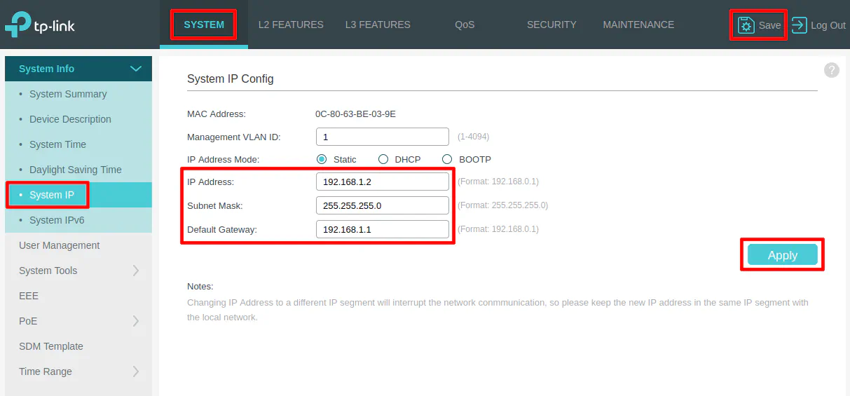
Click “Apply”. You will likely lose connectivity immediately and will have to start using the http://192.168.1.2 web address. You will need to change your device’s IP address to be 192.168.1.10 so it can be on the same subnet as the network switch.
Be sure to log back in and click on the “Save” button in the upper right hand corner to make sure the changes are persistent once you know you are able to connect to the new IP address. If you do not click “Save” on TP-Link switches, the changes will be lost when you reboot the switch.
Physical Diagram of Connected Devices
Before proceeding with the VLAN configuration, refer to the following physical diagram for devices/clients connected to the network (see also the physical network infrastructure diagram). It will be beneficial to see which Ethernet ports the devices are plugged into when configuring the switch.
VLAN Configuration
Go to the “L2 Features” page and click on the “VLAN > 802.1Q VLAN” left side menu to see the list of VLANs. By default, every port is assigned VLAN1 which is designated for untagged ports. The default behavior of a managed switch is exactly like an unmanaged switch so everything is on the same flat network.
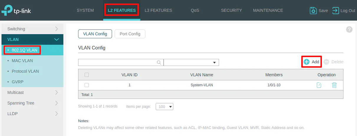
Click the “Add” button to create new VLANs.
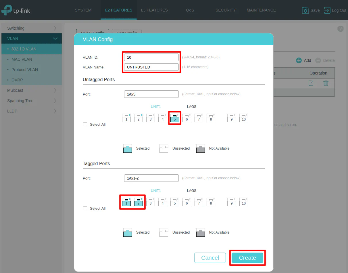
VLAN 10 (UNTRUSTED)
When the “VLAN Config” dialog box opens, you will see two main sections for “Untagged Ports” and “Tagged Ports”. This may be confusing if you are new to VLANs.
The “Untagged Ports” section is where you select the port(s) you wish to add to a particular VLAN for all of your wired devices. You can only have an “untagged port” assigned to a single VLAN.
The “Tagged Ports” section is only used for ports that are connected to VLAN-aware devices such as routers, switches, wireless access points, and even servers (such as virtualization servers). “Tagged ports” can be assigned multiple VLANs unlike “untagged ports” so that multiple VLANs can pass through one port. Think of tagged ports as an aggregation of multiple VLANs. You will often see the term “trunk port” used to refer to the tagged ports.
Enter the “VLAN ID” of 10 for the UNTRUSTED network, and the “VLAN Name” of “UNTRUSTED”. An IoT device such as a smart TV is connected to the UNTRUSTED network on port 5 so it is selected in the “Untagged Ports” section. Select ports 1 and 2 as the tagged ports include the ports connected to OPNsense as well as the wireless access point.
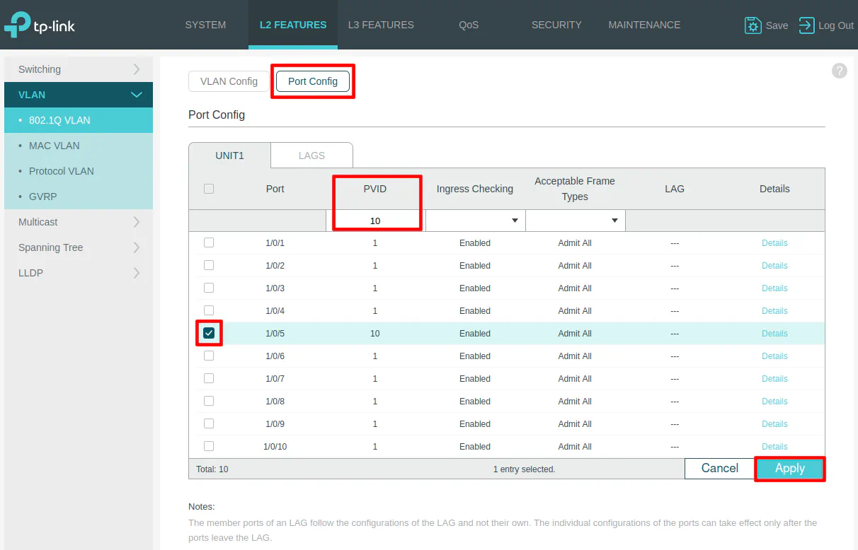
On the “Port Config” section, select port 5 and set the PVID to 10 as the VLAN ID. This step is important. Otherwise, the port will not be properly tagged with the desired VLAN ID.
VLAN 1 (LAN)
The trusted LAN will be on the default VLAN 1 so we do not need to make any changes for the trusted devices which are connected to ports 3 and 4 in the diagram above since those ports are already in the default VLAN 1.
Connect switch to OPNsense and the AP to the Switch
After the switch has been configured, it is time to plug it into OPNsense to see if the VLAN configuration was successful! Plug the LAN interface of OPNsense into port 1 on the switch.
For a quick test of the VLAN, try plugging your device into port 5 and check your device’s IP address. If you receive an IP address in the 192.168.10.x network, then your configuration is working properly!
You may also plug the Grandstream (or other) wireless access point into port 2 before proceeding with the configuration in the next section.
Configure Wireless Access Points
The last device which needs configured is the wireless access point. When using a firewall mini-PC such as the Protectli VP2420, I recommend using external wireless access points rather than using a USB or built-in wireless module on the mini-PC. WiFi performance will be much greater and more reliable when using dedicated wireless access point(s). The APs I prefer to use have a wired backhaul connection.
A wired backhaul means the wireless AP has an Ethernet cable that is plugged either directly into your router or into a switch that is plugged into your router. Many wireless APs can be powered via PoE (Power over Ethernet) in which case you will need to plug it into a PoE network switch or use a PoE injector. Some APs have a barrel jack to plug it into AC power which might be helpful for some users depending on the location of your AP.
Not all wireless access points support creating VLANs but APs such as the Grandstream I am using in this example support this feature. When APs support VLANs, you have the ability to add your wireless devices to the same VLANs as your wired devices, which is convenient since it allows you to group untrusted wired and wireless devices together, for example.
Because OPNsense and the network switch have been configured with a VLAN, all that remains is the VLAN configuration of the AP. There are other parameters you may tweak as well to improve wireless performance, but I am going to focus on the VLAN configuration to get the devices connected. I will leave WiFi performance tuning as an exercise for the reader.
You can connect to Grandstream wireless APs via a built in web interface if you are not using their locally installed or cloud managed controller, which is very convenient when you only need to configure one device.
If you go to the “Services > DHCPv4 > Leases” page in OPNsense, you will be able to find the IP address of the Grandstream AP. The IP address should reside in your trusted LAN such as 192.168.1.104. Simply enter https://192.168.1.104 depending on the IP address that is assigned to the AP.
For Grandstream APs, the default username is admin and the default password is located on the bottom of the AP so you will need to use that for the password.
Create the Trusted Network (LAN) SSID
The first time you log into the Grandstream AP, you will have a basic configuration wizard to set up the device with the first SSID. For the first screen since there is only one AP being configured, you can essentially click “Next”. If you have more than one AP, the nice thing is that you can manage your other APs from the first AP so there is no need to install a local controller.
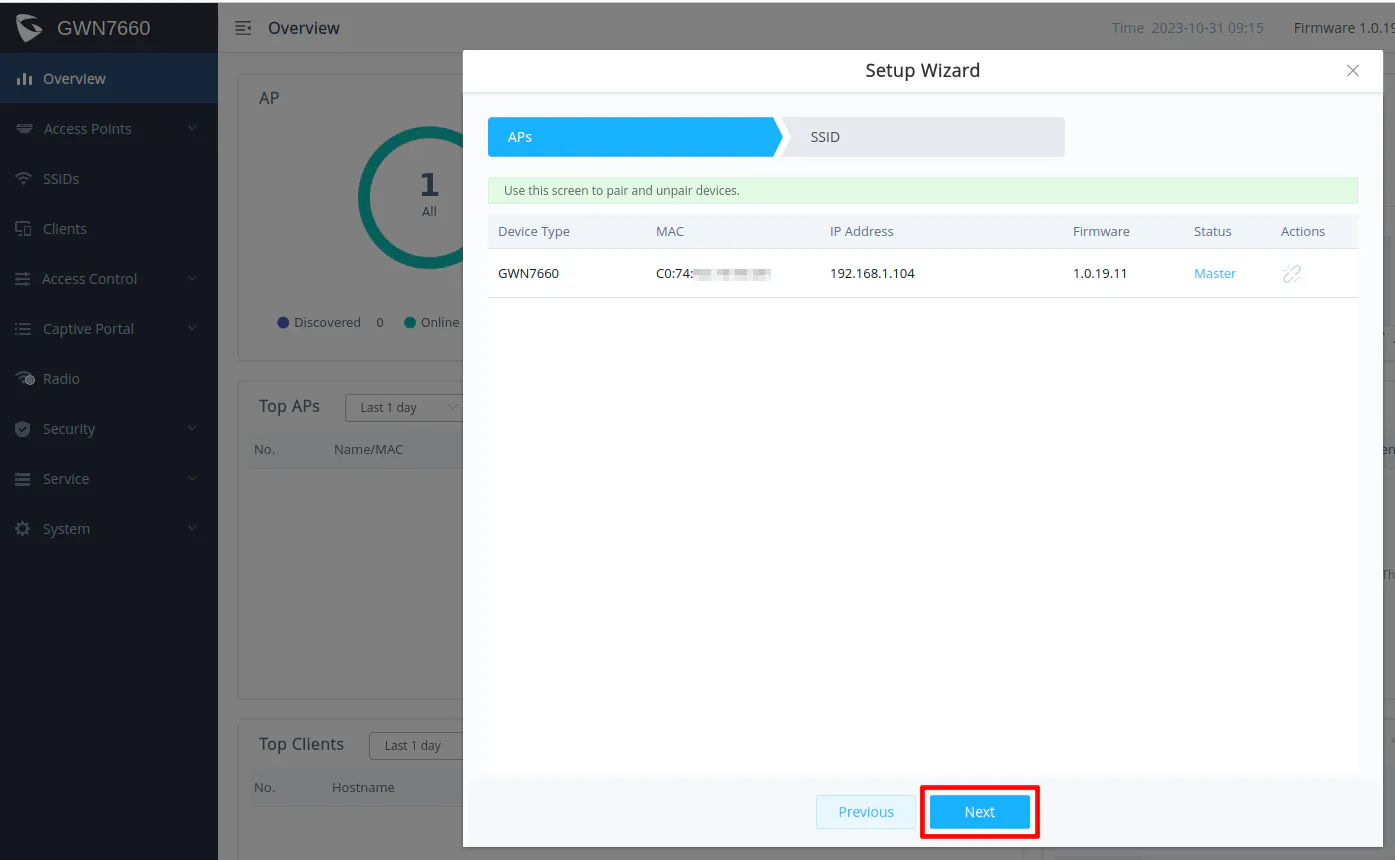
On the second screen, you can configure your first SSID for your wireless network. In the scenario for this guide, I am going to create 2 WiFi networks – one for your trusted network and one for the untrusted network. When you complete the configuration of the first SSID, it will by default be on your trusted network since no VLAN ID is set for the SSID.
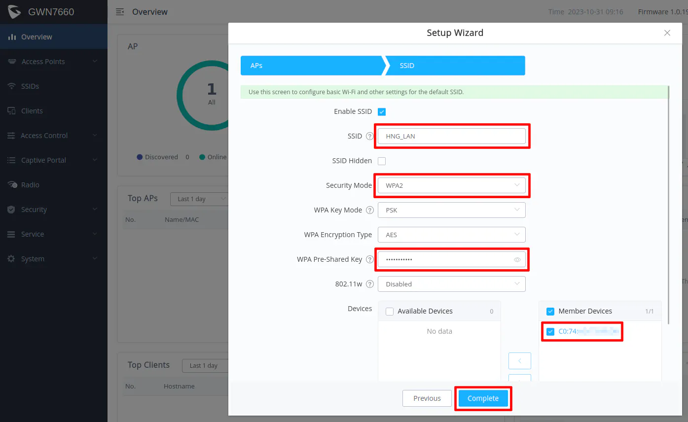
Enter the desired “SSID” and “WPA Pre-Shared Key”, which is the password for your WiFi connection. You will want to name your trusted and untrusted WiFI network as something meaningful to you.
For the “Security Mode”, you may use WPA2 for the greatest compatibility among your clients since not everything may support WPA3. If you have all newer devices, you can likely use WPA3. Some APs offer the option to support both WPA2 and WPA3 simultaneously including the Grandstream AP. That option might be the best of both worlds for compatibility and for improved wireless security since newer devices should hopefully default to WPA3.
Make sure your current device on the “Member Devices” to include your access point. Otherwise the SSID settings will not be applied to your access point (you can fix that later if you forget to check that option).
Click “Complete” to set up the first SSID. You should now have your trusted network SSID set up! If you like, you can try connecting a mobile device to that network to see if you get an IP address in the 192.168.1.x network.
Create the Untrusted Network SSID
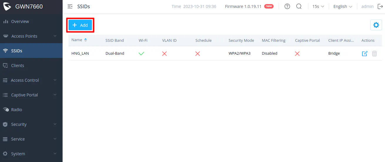
Go to the “SSIDs” page by clicking on the “SSIDs” menu on the left side of the page. You will see the trusted network SSID that was just created. Click on the “Add” button to create a new SSID.
Enter the “SSID” for the untrusted network. You may not want to have “UNTRUSTED” in the name, but I am using that as an illustration to make it clear which network the SSID is on. Check the “Enable SSID” box.
You will need to check the “VLAN” option and enter 10 as the “VLAN ID”. You can select your desired “Security Mode” as described earlier as well as the “WPA Pre-Shared Key” for your password.
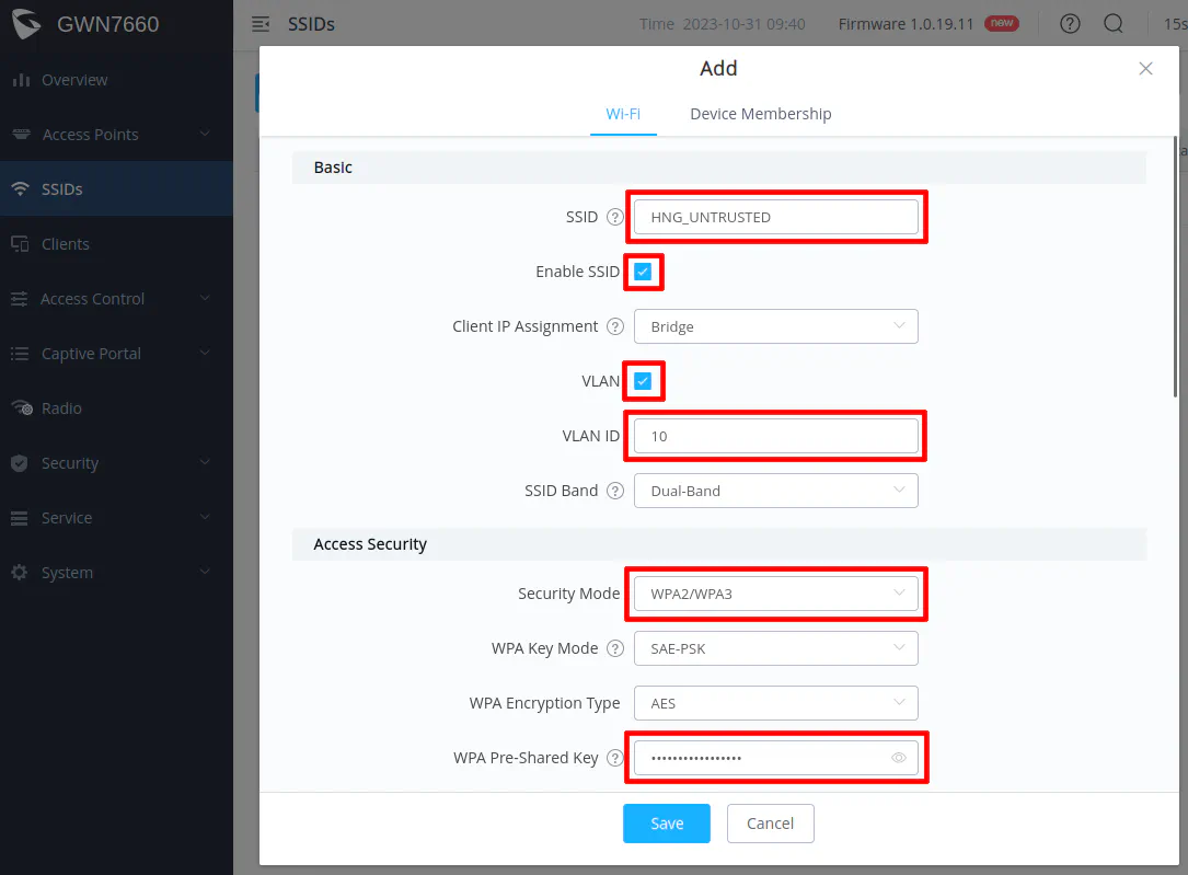
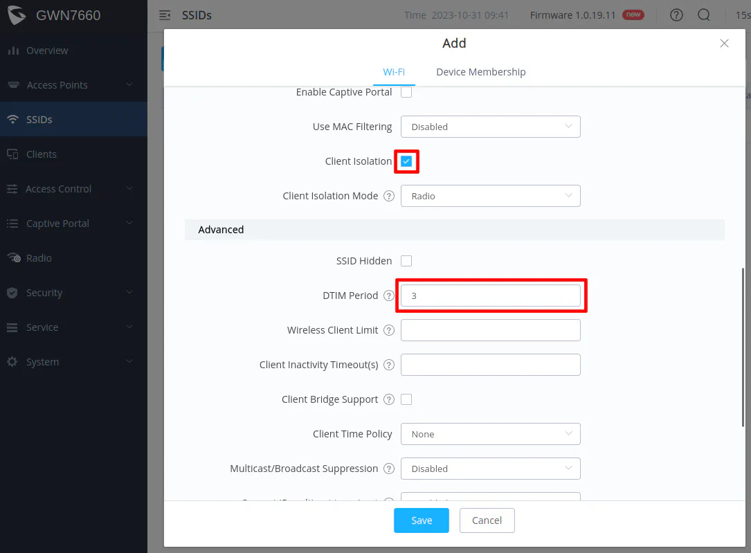
Since the network is untrusted, you may want to consider enabling “Client Isolation” to prevent wireless clients from communicating directly with each other.
I have seen it recommended to set the “DTIM Period” to 3 to help conserve battery usage of mobile devices that are using WiFi.
Before clicking “Save”, go to the “Device Membership” tab at the top of the dialog box. Select the AP in the “Available Devices” and click the right arrow button to move it to the “Member Devices” so that the SSID gets applied to the access point.
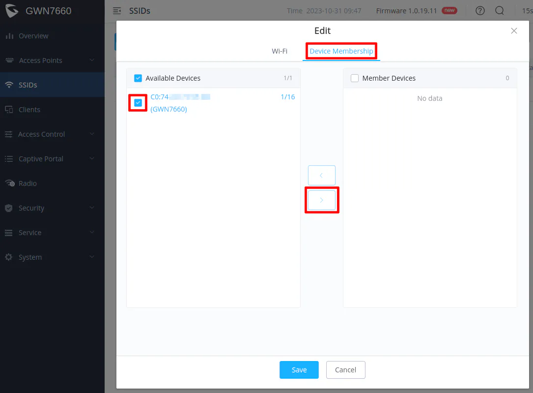
Make sure the device is moved to the “Member Devices” box as shown below before clicking “Save”.
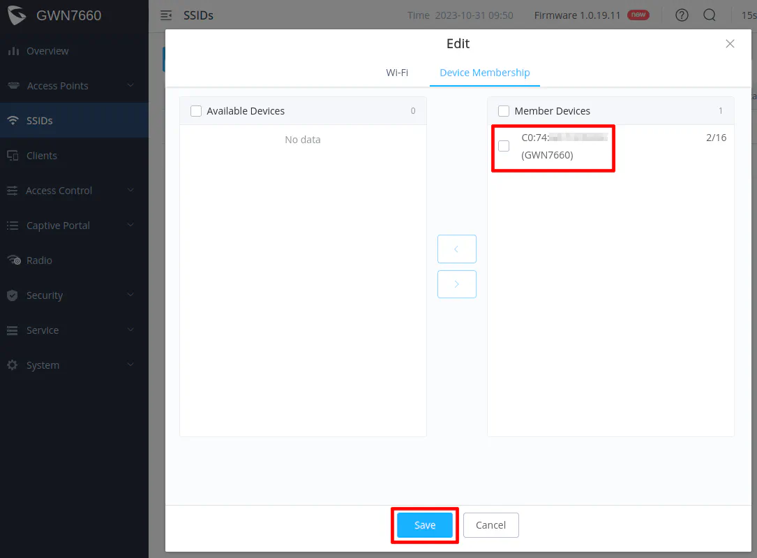
Click “Save” to the configuration of the second SSID. You will also need to click the “Apply” button for changes to take effect on the AP.
You may try connecting to that SSID to see if you get an IP address in the 192.168.10.x network. If you do, the VLAN configuration is working properly!
Next Steps
If all goes well, you should have a fully functioning home network with a trusted LAN and an untrusted VLAN to separate devices that may be more likely to be compromised, which helps to improve the security of your most trusted devices! Congratulations!
My hope is that you found this simplified version of the full network build to be beneficial if you are a novice user. The great thing about your home network is that you are free to build it to meet your wants and needs!
Below are a few ideas of areas to explore next should you find yourself wanting to go further on this journey.
Implementing Additional Security Features
Since you have the basics configured if you followed this guide, you may wish to go deeper into other areas to add more features or to implement more layers of security. As a reference, I have written a guide to discuss several security related features that you may wish to implement on your OPNsense system or your home network.
You may also wish to check out the original full network build guide which covers more advanced networking topics using a more complex network architecture.
Multi-Homing Device(s)
Multi-homing is the concept of placing a single device into two or more separate networks. In order to accomplish this, you need a system with two or more network interfaces. Some mini-PCs and NAS devices include more than one network interface, which is very useful if you wish to multi-home the device.
A NAS is one good example where you may want to multi-home. Routing lots of network traffic through the firewall can slow down performance significantly especially if you are running any intrusion detection/prevention services on the firewall. IDS/IPS requires a great deal of computing power in order to process all of the data packets on the network in a timely fashion.
By putting your NAS on multiple networks where access is needed, you can prevent high bandwidth traffic from traversing across networks and through the firewall. You should consider multi-homing your NAS if firewall performance is suffering. This is a topic I may explore in greater detail in future guides.
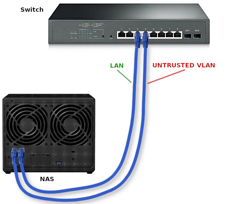
In the diagram below, you would connect both interfaces to your switch but configure each port to be on different networks. If following the example in the guide, you could include the NAS on both the LAN and the UNTRUSTED VLAN. Each network interface would have an IP address in the respective network. Then you would configure client devices on each network to access network shares, for instance, using the corresponding IP address for the NAS for each network. The clients will be able to communicate freely with the NAS without traversing the firewall.
Secure, Remote Access to Your Network
If you are interested in remotely accessing your network for various reasons, you may run IPSec, OpenVPN, WireGuard, or Zerotier using built-in functionality or plugins.
Once you have your VPN set up in OPNsense, you can create firewall rules to allow the desired access to your internal networks. For instance, you may want to create a rule to access all of the devices on your trusted network (the LAN in the example provided in this guide).
I have written guides on OpenVPN and WireGuard if you are interested in setting up those VPN services in OPNsense.