Set Up a Fully Functioning Home Network Using OPNsense

Photo by bluebay2014 from iStock
Table of Contents
Since the publication of this guide, I have written a new guide which is aimed more towards beginners. The beginner’s guide focuses more on the bare minimum requirements to get started with building a full network using OPNsense. In that guide, I only demonstrate using the LAN interface with a single VLAN where untrusted devices may be placed. I feel this would be a good first step in learning how to build a more advanced home network since it provides a basic foundation on which to build upon.
I often write about specific networking topics in an effort to limit the scope of each topic being discussed. However, I thought it would be helpful to create one comprehensive guide which pulls together many concepts to demonstrate how all the pieces fit together using a real world example.
While beginners may follow this guide, this guide is aimed towards individuals which already have some background knowledge on networking but wish to take their home networks to the next level.
Much of this guide will be focused on OPNsense configuration since it lies at the core of the network infrastructure, but I will also discuss managed switches and wireless access points.
When it comes to the network switches and wireless access points, I cannot include an example of all varieties of those products. Therefore, you will have to adapt this guide to the hardware you are using. I personally prefer to use managed network switches which have a web interface for configuration rather than switches which only provide a command line interface (even though I am not personally afraid of using the command line).
Because there is so much to cover, I will attempt to be more concise than usual in certain areas. In some cases I may refer to other guides I have written if you wish to go into more depth about a particular topic.
Disclaimer: Please consider that I am merely presenting one network architecture that may be used as a reference. I am not endorsing or claiming that this architecture is the best way to implement your home network – it is simply one way you could implement it. In the end, you have to decide what meets your needs the best.
Network Architecture
The example network will assume the following architecture:
- The connection from the ISP will utilize a modem or a modem/router in bridge mode (to avoid double NAT)
- The modem is connected to the first port of a four port OPNsense box for the WAN interface
- The LAN interface will be connected to a smart/managed network switch to be used as a dedicated management interface and will only contained untagged network traffic
- Two interfaces on the OPNsense box will be set up as a LAG (Link Aggregation Group) to the network switch to provide extra bandwidth/redundancy across networks and will only contain tagged VLAN traffic
- A wireless access point with VLAN support will be connected to the network switch to provide wireless for the networks
- Other devices will be connected to the network switch in various VLANs
- The network will use dual stack IPv4 & IPv6*
In the example described above, it is important to note that the management LAN interface (where all of the critical network infrastructure will be managed) will only have untagged network traffic while the LAG interface will only have tagged VLAN traffic.
Note
Some users prefer to set up a dedicated management VLAN where all network infrastructure can be managed and avoid using the default untagged network, which is often depicted as “VLAN 1” on network switches. The primary reason is the security concern of users plugging devices into ports that are not assigned to any VLANs since they would have access to the most sensitive part of the network.
When using the default “VLAN 1” as your management network, you need to be sure to assign all unused ports to a VLAN to avoid unwanted devices on your management VLAN. You could assign unused ports to the GUEST network or to a sinkhole network with no network access. You could even disable the ports on the switch but that seems a bit extreme and inconvenient.
For home networks in particular, this risk is likely much lower than on business/enterprise networks especially since most guests in your home typically use WiFi rather than plugging directly into your network switch (or a wall jack which is connected to your network switch).
Regardless of whether or not you use the untagged LAN or have a separate VLAN for managing your critical network infrastructure, the OPNsense team recommends separating untagged and tagged VLAN traffic so they are not on the same interface to prevent potential security issues due to carelessly written firewall rules on the parent interface. This actually caught several users by surprise including myself.
Do not worry because this guide will demonstrate separating untagged and untagged interfaces by using one of the interfaces on the router/firewall box as a dedicated management interface and the remaining interfaces for VLANs only.
Note
* For the IPv6 configuration demonstrated in this guide, it will be based on the assumptions that the ISP is providing dynamic IPv6 addresses and that IPv6 will only be configured to allow Internet access. Similar to IPv4, the IPv6 networks will be configured to isolate them from each other.
I will not demonstrate using IPv6 for your internal networks in this guide. There are some challenges with using dynamic IPv6 addresses on your internal network especially when IPv6 addresses change. For this reason and more, I will only use IPv4 examples for allowing access between devices. IPv6 configuration will be limited to Internet access only.
Logical Network Diagram
To have a visual representation of what this guide will implement, I have included the following logical network diagram.
Note
Please keep in mind this is a logical diagram so the LAG which has the 5 associated VLANs is only using 2 physical interfaces rather than 3 interfaces. Some users may have interpreted this diagram as “use all of your remaining interfaces in the LAG”.
Depending on your needs, you will likely not see many benefits going beyond 2 interfaces. Even 2 interfaces might be overkill for certain networks if you do not have a lot of traffic going across VLANs.
If you have 2.5 Gbps interfaces or faster on your OPNsense box, you may not need to use any LAGs since you have more bandwidth available, and therefore you can skip over the LAG section in this guide.

Physical Diagram of Network Infrastructure
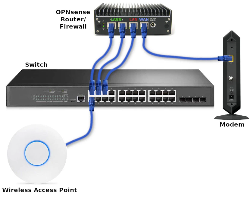
Refer to the image below for the physical connections of the network infrastructure that I will be using.
To keep the physical network infrastructure image less cluttered, the image below only shows the basic network infrastructure described in my example and not the various devices connected to the network (see also the physical diagram of connected devices).
TL;DR Overview
Because this guide will be longer than my usual content, below is an outline of what will be done to complete the full network example I am discussing:
- Install OPNsense
- Configure OPNsense
- Configure network switch
- Configure wireless access point
The full setup may seem daunting, but I am including a lot of configuration information with brief descriptions in an effort to show all of the necessary or recommended values to build a fully functioning network with OPNsense.
Let us get started with installing OPNsense!
Install OPNsense
The first step you need to do is install OPNsense on your desired hardware. I am using a Protectli VP2410 in my network example, but you can use any hardware compatible with OPNsense.
Go to the OPNsense download page. Choose the “vga” installer so you can install it on a USB drive. Use a program such as Etcher to flash the drive with the image you just downloaded (you do not even have to extract the image if you are using Etcher).
To keep this guide shorter, I will not include screenshots in this step like I did with my installation guide.
- Do not press any key when prompted for the configuration importer
- Press any key for manual interface assignment (I prefer to manually configure than using the automatic process)
- Press “Enter” to skip the LAG configuration (will do this later in the web interface)
- Press “Enter” to skip creating VLANs (also will do this later)
- Enter
igb0for the WAN interface name (for the Protectli VP2410 – your interface names may be different) - Enter
igb1for the LAN interface name (for the Protectli VP2410) - When prompted for an optional interface name, press “Enter” to skip configuration (will do this later)
- Press “y” and “Enter” to continue
- At the login prompt, enter the username
installerand the passwordopnsenseto continue with the installation - Press “Enter” to continue with the default keymap (if you are using the US keyboard, otherwise select the appropriate option)
- Select the “Install (ZFS)” option to use the ZFS filesystem
- Select the disk where you want to install it (you should be able to tell the difference between the USB and internal hard drive based on the name and size)
- Select “Yes” to continue with the recommended swap partition size of 8 GB
- Select “Yes” to continue to destroy the current contents of the disk
- Select “Change root password” now so you do not forget (you will use this to log into the web interface or console)
- Enter the password twice
- Select “Complete Install” to finish installing OPNsense
When it is finished, it will reboot and you should see a login screen with the IP addresses of your interfaces.
Configure OPNsense
Before configuring OPNsense, make sure you have your PC, laptop, or other device you wish to use to configure OPNsense plugged into the LAN interface. In our example, that would be the second interface from the right side of the box. The LAN interface will be used as the dedicated interface to manage OPNsense and other network infrastructure.
Warning
If you are setting up OPNsense on new hardware and you are connecting the WAN interface to your existing home network, you need to be careful when configuring your interfaces.
One issue I accidentally encountered is configuring an interface which has the same IP address range of the network where the WAN interface is attached. I was testing configuration similar to my main network and did not think about this issue. This caused an issue with DNS because the WAN of my test system was using the DNS server (192.168.20.1) of the VLAN on my main network and one of my VLANs on my test system was set up to use the 192.168.20.1/24 network. The local interfaces take priority so the WAN DNS no longer worked properly.
For the OPNsense configuration, you will need to login to the default https://192.168.1.1 URL. You could use the default opnsense.local domain, but if you decide to change the host/domain name later when configuring OPNsense, you will have to switch to the new hostname in your browser to continue the configuration. If you use the IP address instead, you will not be interrupted due to an OPNsense host/domain name change.
Configuration Wizard
You will be presented with the configuration wizard when you first log into OPNsense. The configuration wizard is completely optional. In this guide, I will skip using the configuration wizard so that you will know where all of the configuration options are located in case you want to make changes in the future. Click on the OPNsense logo in the upper left hand corner of the page to skip the wizard.
System Configuration
The system settings is a good place to start with configuring OPNsense. I will cover the most common settings you will like want to change, but of course if your needs are different, you can deviate from this guide.
Settings: General
On the “System > Settings > General” page, you can customize a few network-wide settings such as the domain name and DNS settings, which can be confusing since there are a few places where you can configure various DNS options. Of course, these settings are free for you to change to your own personal preferences. I do not expect you to use homenetworkguy.com as your domain name, for instance!
| Option | Value |
|---|---|
| Hostname | router (or choose your own hostname) |
| Domain | homenetworkguy.com (choose your own domain name) |
| Time zone | America/New_York (choose your own time zone) |
| DNS servers | Leave blank |
| DNS server options | Leave both boxes unchecked |
Note
If you are unchecking the default DNS server options and you have your OPNsense router plugged into your main router, DNS may not work until properly until you plug your new OPNsense router into your modem as your main router since I am assuming this router will be on the edge of your network when it is fully configured.
Alternatively, you could leave the default DNS server options in the “General Settings” and enable “Use System Nameservers” on the “Services > Unbound DNS > Query Forwarding” page so that DNS queries are forwarded to your main network’s DNS server. You will have to remember to change them back later once you use the newly configured OPNsense box as your primary router.
Settings: Administration
The “System > Settings > Administration” page contains useful configuration for how you wish to access OPNsense (web, SSH, and console):
Web GUI:
| Option | Value |
|---|---|
| Protocol | HTTPS (should be the default value) |
| HTTP Strict Transport Security | Check “Enable HTTP Strict Transport Security” |
| TCP port | Change to 8443 if exposing an internal web server to the Internet (securely, of course) |
| HTTP Redirect | Leave unchecked unless you are exposing port 80/HTTP to the Internet for the purpose of redirecting to 443/HTTPS |
| DNS Rebind Check | Leave unchecked for security (may interfere with certain name resolutions) |
| HTTP Compression | High (if you have a reasonably fast system) |
| Listen Interfaces | Leave at “All (recommmended)” |
Secure Shell:
| Option | Value |
|---|---|
| Secure Shell Server | Check “Enable Secure Shell” (to allow access to OPNsense via SSH) |
| Root Login | Check “Permit root user login” (since only SSH keys are allowed via the next option below, allowing the root login is much more secure, but you may disable this for extra security) |
| Authentication Method | Uncheck “Permit password login” to improve security (only SSH keys are allowed) |
| SSH port | Leave blank for default port of 22 |
| Listen Interfaces | Leave at “All (recommmended)” |
Console:
| Option | Value |
|---|---|
| Console driver | Check “Use the virtual terminal driver (vt)” |
| Primary Console | Select “VGA Console” (if you plan to connect to a monitor, which I recommend leaving enabled) |
| Secondary Console | Select “Serial Console” (if your device has a serial console) |
| Serial Speed | Most likely the default of 115200 should be ok (but consult your user manual) |
| USB-based serial | Check “Use USB-based serial ports” (if your serial console uses USB) |
| Console menu | Check “Password protect the console menu” to add more protection to console access |
Authentication:
| Option | Value |
|---|---|
| Server | Leave at “Local Database” unless you are using multi-factor authentication |
| Sudo | Choose “Ask password” if you wish to allow other admin accounts you create to have sudo privileges for higher level system access |
| User OTP seed | You can leave this option as “Nothing selected” even with multi-factor authentication enabled if you do not want users to generate their own codes (if you control all user accounts this option is not needed) |
If you changed the “Protocol” to “HTTPS” when you are using “HTTP” or you changed the “TCP port” to a different value, you will need to change the URL you are using to access OPNsense accordingly (if you are not automatically redirected to the new URL).
Settings: Miscellaneous
The “System > Settings > Miscellaneous” page has a few options you may want to tweak such as the CPU type for the thermal sensors widget on the “Dashboard”. There are some periodic backup options, power savings options, and memory/swap options.
| Option | Value |
|---|---|
| Thermal Sensors Hardware | Intel Core CPU (unless you have AMD hardware) |
| Periodic RRD Backup | 24 hours (optional) |
| Periodic DHCP Leases Backup | 24 hours (optional) |
| Periodic NetFlow Backup | 24 hours (optional) |
| Use PowerD | Checked (if you have power saving options enabled in the BIOS) |
| Power Mode | Hiadaptive (to favor performance over power savings) |
If you are using a SSD or a traditional hard disk, you should not need to adjust any of the disk/memory settings at the bottom of the page since those options are more designed for systems where you want to minimize wear on the disk or if disk space is very constrained. Modern SSDs can handle a lot of writes before the disks wear out.
Firmware: Status
If you have your new OPNsense box connected to your primary/existing network while you are setting it up, you may want to update to the latest OPNsense version before proceeding with the rest of the configuration described in this guide. Otherwise, you can perform this step once you complete this guide and you have swapped out your old router with your new OPNsense box.
Go to the “System > Firmware > Status” page and click the “Check for updates” button. It will jump over to the “Updates” tab while checking for updates. If any updates are available, you will be notified.
When you close the information box for an update, you can see at the bottom of the page if the update requires a reboot or not. This is very helpful in determining if you wish to proceed with an update. I will often wait to perform the update when nobody is using the network whenever I see that a reboot is required. Typically smaller updates will not require a reboot, but of course it depends on what part of the system is being updated.
Access: Users
Generally speaking, a security recommendation is to create a new user with administrator privileges rather than using the default root user. Once another user is created, you can actually disable the root user to minimize the likelihood of the root user account being used maliciously.
On the “System > Access > Users” page, click on the “+” button to add a new user. Enter the following information (use your own values where it makes sense):
| Option | Value |
|---|---|
| Username | dustin |
| Password | examplepassword |
| Full Name | Dustin Casto |
| [email protected] | |
| Login shell | /usr/local/bin/bash (to allow shell access) |
| Group Memberships | admins (click admins and the right arrow button) |
| OTP seed | Check “Generate new secret (160 bit)” (if using two factor authentication – requires server described in next section) |
| Authorized keys | Paste a generated SSH key if you plan to use SSH for this account |
If you wish to disable the root user, logout of the root user account and login with your new administrator account. Then go back to the “System > Access > Users” page. Click the pencil button next to the root user and click the “Disabled” check box. Save your changes.
Tip
If you only want to use the root user to log into OPNsense via console/SSH but not allow the root user access to the web interface, you can simply leave the root user enabled and remove the root user from the admins group. This only revokes the web interface access but not console/SSH access for the root user.
If you leave SSH password authentication disabled and only use SSH keys, your root account should still be more secure than using a password.
Note that you can only remove the root user from the admins group after creating another admin account.
After you save your account, you will be able to click the “Click to unhide” button for the “OTP QR code” option which is now visible. This allows you to use a QR code to add the TOTP to your favorite authenticator application on your phone or other device. If you are using a password manager, you can copy/paste the “OTP seed” to be able to generate codes from your password manager.
Access: Servers
The access servers in OPNsense allow you to add different authentication methods such as timebased one time password (TOTP) to enable two factor authentication. On the “System > Access > Servers” page, click on the “+” button to add a new authentication method. Enter the following values:
| Option | Value |
|---|---|
| Descriptive name | TOTP server |
| Type | Local + Timebased One Time Password |
| Token length | 6 (the default value) |
| Reverse token order | Checked |
By default the token needs to be entered before the password, but if you check the “Reverse token order” option, the token should be entered after the password.
The reason I prefer to add the 6 digit token at the end of the password is that it works great for password managers such as BitWarden since the token is automatically copied to the clipboard after the username/password is filled it on the page. That allows you to click the password manager’s “auto fill” button and then immediately issue a “Ctrl + V” to paste the token to the end of the password. I find that to be convenient if you utilize password managers that also store the tokens.
Some users prefer not to store their second factor token in the same location as their passwords, which is certainly understandable from a security standpoint.
Note that at this point two factor authentication is not enabled yet. Before enabling it, you should test out the two factor authentication first, which leads us to the next section below.
Access: Tester
The “System > Access > Tester” page allows you to test out your other authentication methods before enabling them, which is very handy. You do not want to inadvertently lock yourself out the system.
To test out the TOTP server you just created, select the “TOTP server” from the dropdown menu. It will be named whatever you called it in the “Descriptive name” from the previous step. Simply enter the username and password + token of the admin user you just created. You will receive a pass/fail message after testing the user.
Access: Users (Again)
If the login for the new admin user passes the test from the previous step, log out and log back in as the new admin user before proceeding.
You can now remove the root user from the admins group to revoke root user access to the web interface. Go back to the “System > Access > Users” page, and click the pencil edit button for the root user.
For the “Group Memberships” option, click on “admins” in the “Member Of” box and click the left arrow to move it to “Not Member Of”. Click the “Save” button to persist the changes. You will no longer be able to log into OPNsense using your root user!
Keep in mind that you can still log into the server as the
rootuser via the console or SSH if you have left it enabled earlier. If you allowrootuser access for SSH, I recommend using only SSH keys and disabling the password for SSH access to keep yourrootuser account more secure.
Tip
If you are using your non-root user admin account when logging into SSH or the console, you can still access the same root user menu by entering the sudo su command. After entring your password, you will see the same menu options that is shown to the root user. For this command to work, you will need to ensure you have the “Sudo” option enabled on the “System > Settings > Administration” page.
Interface Configuration
Next up is configuring the interfaces. I highly recommend you consider how you want to layout your network before creating the interfaces because you may find that it is very disruptive to reconfigure the interfaces at a later time since it likely involves temporarily taking down some or all of your network.
In this example, I will be configuring a LAG interface to demonstrate the process, but you may skip this section and go to the VLAN section if you do not want to use a LAG interface. The process of creating VLANs is the same whether or not you are using a LAG interface. The only difference is the physical interface you choose to associate to the VLAN.
Note
If you plan to use Zenarmor, I highly recommend you test if LAGs will function properly before committing to using a LAG. Since I tested my OPNsense configuration on a separate system wile using my old firewall appliance, I could verify that the LAG would function well with Zenarmor.
Your mileage may vary depending on the type of hardware you are using since there may be issues with netmap that prevent certain types of network interfaces from working properly in LAGs. You may be safe if you have igb based 1G interfaces such as those found on the Protectli VP2410 because it has been stable for me for an extended period of time.
Also in discussions on Twitter, it was mentioned that perhaps issues are more likely to occur with LAGs on networks that have heavy traffic on a regular basis such as saturated business/enterprise networks.
Interfaces: Settings
| Option | Value |
|---|---|
| Hardware CRC | Check “Disable hardware checksum offload” (if not already checked) |
| Hardware TSO | Check “Disable hardware TCP segmentation offload” (if not already checked) |
| Hardware LRO | Check “Disable hardware large receive offload” (if not already checked) |
| VLAN Hardware Filtering | Choose the “Disable VLAN Hardware Filtering” option |
I have often seen the recommendation to disable hardware offloading on the network interfaces due to various issues that may be encountered. For most users, it is always best to leave it off unless you have thoroughly tested out these configuration options.
In a home network, hardware offloading (if it works) is likely less impactful than using it on a heavily saturated business or enterprise network unless you regularly saturate your network’s bandwidth.
If you are using IDS/IPS services such as Suricata or Zenarmor, hardware offloading should be disabled since it is incompatible with netmap.
Other Types: LAGG
As mentioned earlier, I am going to assume a default OPNsense installation where only the WAN and LAN interfaces are enabled and the remaining interfaces were not assigned during installation. You should be connected to the LAN interface while configuring the interfaces in OPNsense. This allows you to easily change the interface configuration without dropping your connection or accidentally locking yourself out. Hence, the advantage of dedicating one of the network interfaces for management and administration purposes as described in this guide!
The Protectli box in my example has 4 interfaces, which means I am able to use the remaining 2 interfaces to create a LAG interface. Go to the “Interfaces > Other Types > LAGG” page and click on the “+” button to configure a LAG interface.
In order to assign the parent interfaces to a LAG, they must not be currently assigned. The dropdown box will only show interfaces which are allowed to be added to a LAG interface.
| Option | Value |
|---|---|
| Parent interface | Select the interfaces to be in a LAG (in this example: igb2 and igb3) |
| Lag proto | LACP (you will need a switch which supports LACP – configuration is described later) |
| Description | VLAN LAG (you may enter your own value here) |
| MTU | Leave blank to use default value |
Other Types: VLAN
With the LAG created, you can now create the VLANs that will be associated to the LAG interface. Once the VLANs are associated to the LAG interface, you will be able to assign VLAN interfaces in the same way as physical interfaces as shown in the next section.
In this example, I am going to create several VLANs to demonstrate different use cases you may want to use in your network. You definitely do not need to have this many VLANs or you can create even more than what I have shown. Think about the types of devices you wish to isolate and create the appropriate VLANs. You may find it helpful to consider the function of the devices when creating VLANs. Devices which perform similar functions and need to have similar restrictions/access are good candidates for being on the same network.
For the purposes of this guide, the following VLANs will be created along with some of the reasons why you may want such a VLAN on your network:
| VLAN Tag | VLAN Description | Purpose |
|---|---|---|
| 10 | DMZ | For anything you want to expose to the Internet |
| 20 | USER | For PCs, laptops, phones (to isolate from IoT devices) |
| 30 | IOT | For Internet of Things (IoT) devices to protect other parts of your network |
| 40 | GUEST | Guest network for visitors/untrusted devices |
| 50 | IPCAM | Isolated network for IP cameras (for local access only) |
Create the VLANs by navigating to the “Interfaces > Other Types > VLAN” page. To minimize the length of this guide, repeat the following configuration below for each VLAN in the table above:
| Option | Value |
|---|---|
| Device | Leave empty to automatically generate a name |
| Parent | lagg0 (use the LAG interface as the parent for all VLANs) |
| VLAN tag | Use the values in the table above for each VLAN |
| VLAN priority | You may use the default “Best Effort” or select priorities (not sure how much it impacts actual performance) |
| Description | Use the values in the table above for each VLAN (or use your own) |
Interfaces: Assignments
After the VLANs are created, you will be able to assign them to interfaces. You can think of an “interface” as not only the address of the physical port itself but also an entirely separate network. That concept may seem confusing to new users, but creating a new interface assignment is how you create separate physical or logical networks in OPNsense (and other router platforms). When creating an interface you can specify the size of the network, which limits the total number of devices that can be connected to each network. The interface acts as the gateway for each network where traffic may enter or exit.
On the “Interfaces > Assignments” page, you can create a new interface by clicking on the “+” button in the “New interface” section of the page. The dropdown box only shows unassigned physical/logical interfaces. Once you assign the interface, it will no longer be included in the dropdown.
The WAN and LAN interfaces should already be assigned from the OPNsense installation so I will only mention setting up the VLAN interface assignments.
Select each VLAN listed in the table below in the “Network port” dropdown box and add the appropriate “Description”. The “Description” is displayed on the “Interfaces” section in the left side menu so it is important to use a short name to indicate the purpose of each network. Otherwise, they will show up as “OPT1”, “OPT2”, etc., which will be very confusing when you have multiple networks to manage.
| Network Port | Description |
|---|---|
| vlan01 DMZ (Parent: lagg0, Tag: 10) | DMZ |
| vlan02 USER (Parent: lagg0, Tag: 20) | USER |
| vlan03 IOT (Parent: lagg0, Tag: 30) | IOT |
| vlan04 GUEST (Parent: lagg0, Tag: 40) | GUEST |
| vlan05 IPCAM (Parent: lagg0, Tag: 50) | IPCAM |
Click the “Save” button when you are finished.
Tip
I have seen mention of resolving performance issues by assigning the physical parent interface when the parent interface is not being utilized. If you are experiencing poor performance across your VLANs, you may need to assign the parent interface without fully configuring the interface.
Personally, I have not noticed this issue with the Protectli VP2410 and the network configuration described in this guide. I tried assigning/unassigning the parent interface with no noticeable impact to performance.
Interface Pages
Each interface has its own page under the “Interfaces” menu on the left side of the OPNsense user interface. They will appear as [WAN], [LAN], etc. Go to the appropriate interface pages below to modify the configuration described below.
Interfaces > [WAN]
For the WAN interface, you may not have to change much of the configuration especially if your ISP uses DHCP, but for the sake of completeness I will list out the configuration settings with brief explanations for your reference.
| Option | Value |
|---|---|
| Enable | “Enable Interface” should be checked by default by the OPNsense installation |
| Lock | Check “Prevent interface removal” so you cannot easily remove the interface from the “Interfaces > Assignments” page |
| Description | WAN (the default value from the OPNsense installation) |
| Block private networks | Checked (should be checked if connected directly to the Internet, otherwise you should uncheck it) |
| Block bogon networks | Checked (should be checked if connected directly to the Internet, otherwise you should uncheck it) |
| IPv4 Configuration Type | DHCP (if your ISP uses DHCP) |
| IPv6 Configuration Type | DHCPv6 (if your ISP uses DHCP) |
If you want to use IPv6 with your VLANs and your ISP supports prefixes greater than /64 (such as Comcast Xfinity), you may enter configuration similar to the following under the “DHCPv6 client configuration”:
| Option | Value |
|---|---|
| Request only an IPv6 prefix | Unchecked |
| Prefix delegation size | 60 |
| Send IPv6 prefix hint | Checked |
| Use IPv4 connectivity | Unchecked |
| Use VLAN priority | Disabled |
Interfaces > [LAN], [DMZ], etc.
For the LAN/VLAN interfaces, use the following common values for the options of every interface:
| Option | Value |
|---|---|
| Enable | “Enable Interface” should be checked by default by the OPNsense installation |
| Lock | Check “Prevent interface removal” so you cannot easily remove the interface from the “Interfaces > Assignments” page |
| Block private networks | Unchecked (all internal networks should have this unchecked) |
| Block bogon networks | Unchecked (all internal networks should have this unchecked) |
| IPv4 Configuration Type | Static IPv4 |
| IPv6 Configuration Type | Track Interface (if your ISP allows prefix delegations) |
| IPv4 Upstream Gateway | Auto-detect |
| IPv6 Interface | WAN |
| Manual configuration | Check “Allow manual adjustment of DHCPv6 and Router Advertisements” |
And use the following IPv4/IPv6 values in the table below for each corresponding interface:
| Interface | Description | IPv4 address | IPv6 Prefix ID |
|---|---|---|---|
| [LAN] | LAN | 192.168.1.1/24 | 0 |
| [DMZ] | DMZ | 192.168.10.1/24 | 1 |
| [USER] | USER | 192.168.20.1/24 | 2 |
| [IOT] | IOT | 192.168.30.1/24 | 3 |
| [GUEST] | GUEST | 192.168.40.1/24 | 4 |
| [IPCAM] | IPCAM | 192.168.50.1/24 | 5 |
DHCP Configuration
Once the interfaces are enabled, you will most likely want to enable DHCP on the interfaces so that all of your devices will automatically be assigned IP addresses when they are plugged into your network switch or join your WiFi network.
For the DHCP settings, you may want to enable a wider range of IP addresses if you have more than 100 devices on any of your networks, but for most users the ranges I specify below should be sufficient.
If you plan to have some devices use static IP addresses (which is recommended when hosting various apps/services on your network), I recommend that you do not set the DHCP IP address range to include the full subnet (192.168.1.2 - 192.168.1.254, for example) so that you have some available addresses for static IPs.
Do not forget to click the “Save” button after configuring each interface.
DHCPv4
To reduce the length of this guide, refer to the table below to enter the IP address ranges for each interface’s DHCPv4 page by going to the “Services > DHCPv4” menu and clicking on each interface’s page.
For every interface below, be sure to click the “Enable” checkbox.
| Interface | Range from | Range to |
|---|---|---|
| [LAN] | 192.168.1.100 | 192.168.1.200 |
| [DMZ] | 192.168.10.100 | 192.168.10.200 |
| [USER] | 192.168.20.100 | 192.168.20.200 |
| [IOT] | 192.168.30.100 | 192.168.30.200 |
| [GUEST] | 192.168.40.100 | 192.168.40.200 |
| [IPCAM] | 192.168.50.100 | 192.168.50.200 |
Add at the bottom of the each interface’s page, click the “+” button to add static DHCP reservations for devices that are hosting apps/services or devices where you wish to apply specific firewall rules (although you can use hostnames in firewall aliases for clients with dynamic IP addresses, I have found it to be problematic at times – a static IP is the most reliable approach).
You can also add static DHCP reservations directly from the “Services > DHCPv4 > Leases” page. It has the added benefit of prefilling the MAC address. Either way, you will need to enter the same information.
For demonstration purposes, I will use several static DHCPv4 IP reservations that will be referenced by firewall rule aliases and included in several firewall rules. I am using randomly generated MAC addresses in the table as examples, but you will need to use your actual MAC addresses.
| Interface | MAC address | IP address | Hostname |
|---|---|---|---|
| [DMZ] | 0e:66:c8:ee:a8:ee | 192.168.10.10 | webserver |
| [USER] | 00:49:c0:9b:a8:cc | 192.168.20.10 | pc |
| [IOT] | 3e:03:06:01:45:d3 | 192.168.30.10 | printer |
| [IPCAM] | ee:f2:4d:ca:92:44 | 192.168.50.10 | ipcam1 |
| [IPCAM] | c3:c7:cb:db:66:d6 | 192.168.50.11 | ipcam2 |
| [IPCAM] | 23:d1:6f:17:31:8e | 192.168.50.12 | ipcam3 |
DHCPv6
As with DHCPv6 to reduce the length of this guide, refer to the table below to enter the IP address ranges for each interface’s DHCPv6 page by going to the “Services > DHCPv6” section and clicking on each interface’s page.
For IPv6 addresses, you may specify only the second half of the address such as ::1000. The first half of the address is used by default and if you only specify 1 segment, the rest are filled with zeroes (it is how IPv6 notation works to allow shorter addresses to be expressed).
For every interface below, be sure to click the “Enable” checkbox.
| Interface | Range from | Range to |
|---|---|---|
| [LAN] | ::1000 | ::2000 |
| [DMZ] | ::1000 | ::2000 |
| [USER] | ::1000 | ::2000 |
| [IOT] | ::1000 | ::2000 |
| [GUEST] | ::1000 | ::2000 |
| [IPCAM] | ::1000 | ::2000 |
Warning
You will not be able to assign the above ranges for DHCPv6 when you are using DHCPv6 on the WAN interface and “track interface” for each local network interface (LAN, DMZ, etc.) as shown in this guide unless the OPNsense box is connected to your modem. Otherwise if you are not connected, there will be no available IPv6 address ranges to assign since they are assigned by the ISP. You will see an error message on the page that says there are no addresses available to assign. Once you are connected to your modem and have DHCPv6 addresses assigned by the ISP, you should be able to complete this step.
Router Advertisements
For IPv6, there is an additional step which I think is good to do in order to help support all possible IPv6 clients on your network. I like to set the “Router Advertisements” to “Assisted” so that both DHCPv6 and SLAAC is used because not all clients may support DHCPv6.
Although I have learned a lot about how to configure IPv6 in OPNsense, I still do not consider myself to be an IPv6 expert, which is why I am providing a more general IPv6 configuration.
Go to each interface’s page under the “Services > Router Advertisements” section. The first option is “Router Advertisements”. Simply choose “Assisted” and click “Save”. This step is the same for all of the local networks.
DNS Configuration
I think configuring the DNS options in OPNsense can be a bit confusing for new users (I struggled at first too) primarily because there are a couple of places where you may specify DNS information. There are various approaches to how you may configure DNS so depending on the approach taken is where you need to enter the DNS configuration.
You may simply use the ISP’s DNS servers (that is the default DNS configuration in OPNsense), external DNS over TLS (DoT) servers, or another internal DNS server such as Pi-hole or AdGuard Home (which then may use external DoT/DoH servers). In this guide, I am going to configure Unbound DNS as the primary local DNS server which then uses DNS over TLS as the upstream, external DNS servers.
As I briefly mentioned earlier in this guide, I am going to assume you have no DNS servers configured on the “System > Settings > General " page and that you have the 2 “DNS server options” unchecked (to ensure the ISP DNS servers are not being used as the upstream/external DNS servers). Since DNS over TLS is going to be configured in the Unbound DNS settings, the system DNS servers do not need to be specified.
Unbound DNS: General
On the “Services > Unbound DNS > General” page, set the following configuration values:
| Option | Value |
|---|---|
| Enable | Check “Enable Unbound” (if not enabled already) |
| Listen Port | Leave as default 53 |
| Network Interfaces | Choose “All (recommended)” (should be default) |
| DNSSEC | Check “Enable DNSSEC Support” |
| DHCP Registration | Check “Register DHCP leases” (to use hostnames of DHCP clients) |
| DHCP Static Mappings | Check “Register DHCP static mappings” (to use hostnames of static DHCP clients) |
| IPv6 Link-local | Check “Register IPv6 link-local addresses” |
| DNS Cache | Check “Flush DNS cache during reload” (to clear the cache after making changes to Unbound) |
| Local Zone Type | transparent (the default value) |
Click the “Save” button at the bottom of the page and then click the “Apply changes” button at the top of the page to reload the Unbound service to apply configuration changes.
Unbound DNS: Advanced
You may want to set a few of the “advanced” options especially if you are interested in looking at DNS logs in more detail.
| Option | Value |
|---|---|
| Prefetch Support | Checked (increases DNS queries and CPU load slightly so consider your hardware resources) |
| Prefetch DNS Key Support | Checked (increases CPU load slightly so consider your hardware resources) |
| Log Queries | Checked (if you want to troubleshoot DNS lookups or verify DoT is working by seeing DNS servers/ports being queried) |
| Log Level Verbosity | Level 2 (to see more log detail such as the DNS servers being used which helps verify DoT configuration) |
For the logging of queries and the log levels, you may only want to temporarily change these settings to verify DNS is operating as expected since this can be slightly detrimental to performance on slower hardware. It would also add more wear to the disks due to increased logging, which may be important depending on the hardware you are using. I find the DNS query logging useful when verifying DNS over TLS configurations since I can see that it is reaching out to the Cloudflare DNS servers on port 853, which is the port used by DoT for encrypted DNS queries.
Click “Apply” to persist the changes.
Unbound DNS: DNS over TLS
I prefer to use encrypted DNS queries for all outbound DNS queries since it is designed to not only enhance the privacy by limiting tracking of your DNS lookups, but it also offers improved security by reducing the likelihood your DNS queries will be hijacked via man in the middle attack. With a DNS over TLS (DoT) connection, you essentially have an encrypted tunnel to the configured DNS servers. I will be using Cloudflare in my example.
Navigate to the “Services > Unbound DNS > DNS over TLS” page to begin configuring DoT. Click on the “+” button to add a new DoT server. Cloudflare provides several different servers some of which provide additional filtering. Since I am using Zenarmor, I prefer to use the unfiltered Cloudflare servers because it is one less area I need to troubleshoot in case something is inadvertently blocked. The visibility of what Cloudflare blocks is not seen in OPNsense because Cloudflare does the filtering on their end unlike Zenarmor, Pi-hole, or AdGuard where you can see the queries which are being blocked.
Below is the list of DNS over TLS servers you may use for both IPv4 and IPv6. I recommend you include at least 2 DNS servers for IPv4 and at least 2 DNS servers for IPv6 for redundancy:
| DNS Filter | Server IP | Server Port | Verify CN |
|---|---|---|---|
| No filter | 1.1.1.1 | 853 | cloudflare-dns.com |
| No filter | 1.0.0.1 | 853 | cloudflare-dns.com |
| No filter | 2606:4700:4700::1111 | 853 | cloudflare-dns.com |
| No filter | 2606:4700:4700::1001 | 853 | cloudflare-dns.com |
| Malware | 1.1.1.2 | 853 | security.cloudflare-dns.com |
| Malware | 1.0.0.2 | 853 | security.cloudflare-dns.com |
| Malware | 2606:4700:4700::1112 | 853 | security.cloudflare-dns.com |
| Malware | 2606:4700:4700::1002 | 853 | security.cloudflare-dns.com |
| Malware + Adult | 1.1.1.3 | 853 | family.cloudflare-dns.com |
| Malware + Adult | 1.0.0.3 | 853 | family.cloudflare-dns.com |
| Malware + Adult | 2606:4700:4700::1113 | 853 | family.cloudflare-dns.com |
| Malware + Adult | 2606:4700:4700::1003 | 853 | family.cloudflare-dns.com |
Use the information above to fill in for each DoT server you wish to use. You may leave the “Domain” box empty so all lookups go through the same DoT servers since that option is only used if you want a specific domain name (such as homenetworkguy.com) to use a specific DoT server when performing DNS lookups.
Firewall Configuration
The time has come to create firewall rules. Firewall rules are critical for providing increased security among the devices in your network. Having a solid understanding in this area will be crucial in helping you lock down your network tighter.
As you likely know, no software or hardware is fully impenetrable, which is why it is important to have several layers of defense when protecting your network.
I decided to include several VLANs in this guide in order to demonstrate different types of networks you may want to implement in your home network. They should provide some good use cases for how the firewall rules may look different for the types of access desired. Of course, you do not need to implement all of these VLANs in your network.
Note
I will be making use of firewall aliases in the firewall rules below, so if you see a name instead of an IP address for the “Source” or “Destination” it means I am using either a built-in firewall alias or the custom firewall aliases I describe in the “Firewall: Aliases” section.
The names in the firewall rules are not hostnames of devices on the network because hostnames can only be used in firewall aliases. Firewall rules only allow you to enter a single IP/network address or a single firewall alias (aliases may contain more than one value). If you want to use multiple IP addresses or network addresses in a single firewall rule, you have to create an alias containing those addresses and use that alias in the firewall rule.
Firewall: Aliases
The first alias you should create is one which contains all of your networks so you can use the alias to isolate your networks. If you are only using private IPv4 addresses and/or you have static IPv6 addresses, you could simply use all of the RFC 1918 private IPv4 address ranges and your static IPv6 address range so that any future networks you create will also be isolated and protected. When adding new networks it can be easy to forget to include the new network in the alias unless perhaps you create a checklist as a reminder of what you need to do each time you add a new network.
Create a new firewall alias by visiting the “Firewall > Aliases” page and clicking the “+” button at the bottom of the page. For IPv4 addresses and static IPv6 addresses, you could create the following PrivateNetworks alias:
| Option | Value |
|---|---|
| Enabled | Checked |
| Name | PrivateNetworks |
| Type | Network(s) |
| Content | 10.0.0.0/8,172.16.0.0/12,192.168.0.0/16,(include your static IPv6 range if you have one) |
| Description | All local networks |
However, if you are using IPv6 networks which are (unfortunately) dynamic as is the case with my ISP, you will need to add all of your networks using the automatically generated network aliases to the PrivateNetworks alias so that the dynamic IPv6 network addresses will be kept up to date without requiring you to continually update this alias.
When you start writing firewall rules, you will quickly notice that aliases such as “LAN net” and “DMZ net” are created automatically based on the interface names. If you try to create your alias and include “LAN net”, you will realize that you cannot select them from the dropdown menu.
In my previous version of this guide, I recommended creating an firewall group so that you can include the group’s network alias in your PrivateNetworks alias as a workaround for this issue (there is nothing wrong with what I did, but it added extra unnecessary steps). If you plan to have common firewall rules that apply to all your networks, you may still want to create the firewall group so you do not have to repeat as many rules across multiple interfaces.
Someone mentioned in the comments below that you can add the automatically generated network aliases if you type __ in the “Contents” box. I thought I tried that before, but I may have overlooked it when preparing all of the details for this large guide. When you start typing the underscores, you will not see “LAN net” but rather __lan_network for the LAN and __opt1_network for your VLAN network(s).
By using these built-in network aliases, the dynamic IPv6 values will be refreshed automatically when your IPv6 addresses change. These aliases also contain the IPv4 private networks so you do not need to include the RFC 1918 private addresses unless you are worried you will forget to update this alias when you add a new network. Most likely, you may end up noticing it as you are configuring your networks or you discover access is allowed or denied when it should not be.
You should use either the PrivateNetworks alias above or the one below depending if your ISP assigns dynamic IPv6 addresses or not. Remember, if you choose the second option below, you will need to keep it updated when you add new networks unlike the option above (because the option above, all possible IPv4 and IPv6 addresses are known and therefore do not need to change).
| Option | Value |
|---|---|
| Enabled | Checked |
| Name | PrivateNetworks |
| Type | Network(s) |
| Content | __lan_network, __opt1_network, __opt2_network, __opt3_network, __opt4_network, __opt5_network |
| Description | All local networks |
Now for the sake of illustration purposes, I will refer to the following aliases in subsequent firewall rules to demonstrate the types of rules you may want to create to allow access to certain devices/apps across your networks.
A webserver that will be placed in the DMZ network:
| Option | Value |
|---|---|
| Enabled | Checked |
| Name | WebServer |
| Type | Host(s) |
| Content | 192.168.10.10 |
| Description | A local web server |
A PC that will be placed in the USER network:
| Option | Value |
|---|---|
| Enabled | Checked |
| Name | PC |
| Type | Host(s) |
| Content | 192.168.20.10 |
| Description | A PC |
A printer which is connected to the IOT network via Ethernet or WiFi (I recommend enabling the MDNS plugin so the printer can be automatically discoverable across your networks):
| Option | Value |
|---|---|
| Enabled | Checked |
| Name | Printer |
| Type | Host(s) |
| Content | 192.168.30.10 |
| Description | A printer |
Several IP cameras on the IPCAM network (notice you can use IP address ranges if you have your devices sequentially addressed):
| Option | Value |
|---|---|
| Enabled | Checked |
| Name | IPCameras |
| Type | Host(s) |
| Content | 192.168.50.10-192.168.50.12 |
| Description | IP security cameras |
Click the “Apply” button to ensure the alias changes are applied. If you do not click “Apply”, the new aliases will not be available to select when creating firewall rules.
Firewall: Rules: Floating
Floating rules are very helpful when you want a rule to apply to multiple interfaces. They are similar to firewall groups in the sense that the rules can apply to multiple interfaces. I prefer to use floating rules for situations where I have multiple clients on different networks that need access to the same service on one or more servers on my network. You can minimize the need to create the same basic rule on multiple interfaces. Floating rules are also helpful for IP blocklists such as Spamhaus.
One example I personally use is multiple SSH clients needing to access multiple SSH servers. Both the clients and servers are on several different networks. I have firewall aliases for both the SSH clients and the SSH servers so that I only need one floating rule to allow that access. Without this floating rule, the alternative is to create one rule on each interface to allow the clients to access the servers, which would require 2-3 more rules in my case.
For the purposes of this guide, I am only going to create one floating rule for allowing ICMPv6 on all interfaces including the WAN since IPv6 relies more heavily on ICMP than IPv4. The general recommendation is to leave it enabled. You will also receive better scores when testing your IPv6 readiness.
On the “Firewall > Rules > Floating” page, click the “+” button to create a new floating rule. Enter the following information:
| Action | Interface | TCP/IP Version | Protocol | Source | Dest / Invert | Destination | Description |
|---|---|---|---|---|---|---|---|
| Pass | Leave blank for all interfaces | IPv6 | ICMP | any | unchecked | any | Allow ICMPv6 on all networks |
Firewall: Rules: [LAN]
The LAN network will already have the “allow all IPv4” and “allow all IPv6” rules created by default from the OPNsense installation. However, I will tweak them so that access to your other networks is limited. If you recall from earlier, in this example I am using the untagged LAN as the management network where all of the critical network infrastructure will be managed.
Some users like to allow their LANs have full access to every other network and then limit the other networks from accessing the LAN since it can make network administration or access to other systems easier. However, I think it is good practice to also limit the reach of the LAN network even if you are only using as a management network for all of your network infrastructure and services.
Just like any other network, if a compromise happens there, isolating it could still be beneficial to protect other parts of your network (even though it would be very bad if your most critical network is compromised).
Enter the following rules on the “Firewall > Rules > LAN” page in the same order as shown below:
| Action | TCP/IP Version | Protocol | Source | Dest / Invert | Destination | Dest Port | Description |
|---|---|---|---|---|---|---|---|
| Pass | IPv4+6 | TCP/UDP | LAN net | unchecked | LAN address | 53 (DNS) | Allow access to DNS |
| Pass | IPv4 | ICMP | LAN net | unchecked | any | any | Allow ICMPv4 from LAN to all networks |
| Pass | IPv4+6 | any | LAN net | checked | PrivateNetworks | any | Allow access only to Internet |
This will isolate the LAN from the other VLANs in our network and allow access to the Internet. If you want to allow the LAN to reach anything specific in your network, you simply just need to add a rule above the bottom rule.
Since the LAN will be used for network management, I included a rule to allow all ICMPv4 from the LAN to all other networks so that it is possible to use ping and other network utilities for troubleshooting purposes. Note that I am not including ICMPv6 for IPv6 because I already included a floating rule to all ICMPv6 on all networks. IPv6 relies more heavily on ICMP so it is generally not recommended to block ICMPv6.
Many users prefer to block ICMPv4 on their local networks either entirely or only on some of their networks in an attempt to make it more difficult to discover devices on the network. However, in reality it likely does not provide a significant amount of security. Rather than disabling ICMP entirely, you may consider blocking only a subset of ICMP types that may be abused especially in more sensitive networks. For the reasons described on the article linked in this paragraph, you may want to consider enabling ICMPv4 on all networks since it can help improve the responsiveness of your network, waste less network resources, and provide easier troubleshooting on your internal networks.
Firewall: Rules: [DMZ]
The DMZ network will follow a similar patter to the LAN network above. On the “Firewall > Rules > DMZ” page, enter the following values in the same order shown below:
| Action | TCP/IP Version | Protocol | Source | Dest / Invert | Destination | Dest Port | Description |
|---|---|---|---|---|---|---|---|
| Pass | IPv4+6 | TCP/UDP | DMZ net | unchecked | DMZ address | 53 (DNS) | Allow access to DNS |
| Pass | IPv4+6 | any | DMZ net | checked | PrivateNetworks | any | Allow access only to Internet |
Similar to the LAN, this will isolate the DMZ from the other VLANs in our network and allow access to the Internet. In general, you probably should not allow the DMZ to access anything else in your internal network unless perhaps you have a dedicated network just for hosted apps/services and all you have in the DMZ is simply a reverse proxy (I have described this scenario on my reverse proxy guide). The purpose of the DMZ is to limit exposure to your local network if your public facing services are compromised.
Firewall: Rules: [USER]
The USER network can be used for PCs, laptops, or phones (if you do not want phones in your IOT network). The primary purpose is to separate these devices from potentially more vulnerable IOT devices. The rules will be similar to what has been shown until this point except for rules to allow access to devices/services located on other networks.
For the allow rule for the printer, I set the destination port to any to keep it simple but printers can often require several ports depending on the type of printer. For instance, HP printers have a list of ports that you may add in order to further restrict access.
| Action | TCP/IP Version | Protocol | Source | Dest / Invert | Destination | Dest Port | Description |
|---|---|---|---|---|---|---|---|
| Pass | IPv4+6 | TCP/UDP | USER net | unchecked | USER address | 53 (DNS) | Allow access to DNS |
| Pass | IPv4 | TCP | USER net | unchecked | WebServer | 443 (HTTPS) | Allow access to web app |
| Pass | IPv4 | TCP/UDP | USER net | unchecked | Printer | any | Allow access to printer |
| Pass | IPv4+6 | any | USER net | checked | PrivateNetworks | any | Allow access only to Internet |
Ideally, you should have a dedicated device (or VM perhaps) residing on the LAN that has access to all of the web interfaces of your network infrastructure. If you do not have any dedicated devices available, you could create a rule on the USER network to allow your PC/laptop to access the management interfaces. This is less than ideal because you are poking a hole in the management network, but at least access is still restricted from a specific device to specific web interfaces and ports. Security is still better than a flat network with full access to everything.
Firewall: Rules: [IOT]
The IOT network is where you can put less trusted IOT (Internet of Things) type devices or perhaps devices that no longer receive security updates – anything that is likely more vulnerable than your other devices which are regularly updated (PCs, laptops, etc). The reason for such a network is that IOT devices have been notoriously prone to vulnerabilities. They are often developed as cheap, convenient devices which do not receive thorough security audits and are not updated as frequently (or at all if users do not perform updates).
If your phones are on the IOT network, you will likely want the second rule below to allow access to your web app(s) on your DMZ network. To make the rule even more restrictive, you could create an alias that contains the IP addresses of just your phones. To make this work easily, reserving a static IP address via DHCP is one recommendation since you do not have to set it manually on your phone (make sure you turn off private WiFi address options for your local WiFi connection so your MAC address does not change).
The third rule is useful when you want to access your camera feeds from your phone even if you put your IP cameras on their own isolated network which does not have even Internet access. As I mention in the IPCAM section below, any time you open a hole into the camera network, it introduces one more way a malicious user can get in, but I think the risk is pretty low if you limit access and have other protections in place (IDS/IPS, firewall rules, passwords, etc).
| Action | TCP/IP Version | Protocol | Source | Dest / Invert | Destination | Dest Port | Description |
|---|---|---|---|---|---|---|---|
| Pass | IPv4+6 | TCP/UDP | IOT net | unchecked | IOT address | 53 (DNS) | Allow access to DNS |
| Pass | IPv4 | TCP | IOT net | unchecked | WebServer | 443 (HTTPS) | Allow access to web app |
| Pass | IPv4 | TCP | IOT net | unchecked | IPCameras | 554 | Allow access to IP camera feeds |
| Pass | IPv4+6 | any | IOT net | checked | PrivateNetworks | any | Allow access only to Internet |
Firewall: Rules: [GUEST]
The guest network is nice to have if you want to give out access to your WiFi network to guests. You do not know what kind of infestations those users may bring onto your secured network! This network provides you a place that is separate from your network like a DMZ but for untrusted devices that you do not personally own. You can simply allow only Internet access and block access to your local networks (similar to the DMZ – unless the DMZ has access to a dedicated app/services network as I mentioned above) or you could also allow them to access your printer as shown below.
| Action | TCP/IP Version | Protocol | Source | Dest / Invert | Destination | Dest Port | Description |
|---|---|---|---|---|---|---|---|
| Pass | IPv4+6 | TCP/UDP | GUEST net | unchecked | GUEST address | 53 (DNS) | Allow access to DNS |
| Pass | IPv4 | TCP/UDP | GUEST net | unchecked | Printer | any | Allow access to printer |
| Pass | IPv4+6 | any | GUEST net | checked | PrivateNetworks | any | Allow access only to Internet |
Firewall: Rules: [IPCAM]
The IPCAM network is where you can put IP security cameras that is isolated from your network and the Internet. This can be useful if you have a NVR box where you access all your camera feeds. In this network, you could simply allow access to DNS and everything else will be blocked.
You do not really need to create any rules at all to block all access (access is “deny all” by default when no rules exist), but I found that if you allow DNS, the firewall logs are a lot cleaner because you do not see all of the DNS blocks. IP cameras often try to phone home for cloud services so if DNS is blocked they may try even harder to query DNS, which increases spam to your firewall logs. Since all other access is blocked, even if the IP addresses are resolved for domain names, access to external servers is still blocked.
| Action | TCP/IP Version | Protocol | Source | Dest / Invert | Destination | Dest Port | Description |
|---|---|---|---|---|---|---|---|
| Pass | IPv4+6 | TCP/UDP | IPCAM net | unchecked | IPCAM address | 53 (DNS) | Allow access to DNS |
Configure Switch
With OPNsense being configured, you are actually more than halfway done because a bulk of the network infrastructure was completed in OPNsense. You will need a managed or smart network switch that is capable of supporting VLANs in order to make use of VLANs in your network. If you only need basic VLAN functionality, smart switches are often cheaper than managed switches since they offer more basic features than managed switches.
I am going to make the assumption in this guide that you have a new switch that has not been configured or one that you factory reset to the default values. The reason being that an already configured switch will need the current settings changed and it is easier to start at the beginning to learn the steps you need to take.
For a new or reset switch, I recommend that you plug a computer directly into the switch so that you can get it set up before you plug it into OPNsense to avoid any potential issues such as having DHCP running on your switch (it could conflict with DHCP on OPNsense) or a static IP address on the switch which conflicts with the interfaces you have configured in OPNsense.
Connect Directly to Switch
For the configuration of the switch, I recommend plugging into the port that your management LAN/VLAN will be connected to your OPNsense box (in our example, that would be port 6) since you will want to be connected to one of the untagged interfaces so you do not lose connectivity to the switch’s web interface after configuring VLANs (see note below), which then would require you to move over to an untagged port.
As mentioned earlier, you may want a dedicated VLAN for network management, but I am going to demonstrate using the untagged LAN for management (and how you can still make it a safe approach by defaulting unused ports to a VLAN such as the GUEST network – it is a home network so you are free to build it how you feel comfortable securing it).
Note that you can typically configure managed switches to listen on different interfaces so you can still have access to the switch’s web interface from within various VLANs, but since I am configuring a dedicated management network, I do not need to allow web access on different VLANs. That is why I am recommending you to connect to one of the untagged ports for this example.
Once you are plugged into your switch, you will need to determine if your switch has DHCP enabled by default. The easiest way to know is to look at your network status on whatever device you are using to see if you have an IP address assigned. If you do not have an IP address, you will need to manually enter your IP address. However, you will need to consult the manual to see what the default IP address of your switch is set to.
Since I am using a TP-Link managed switch for this example, the default IP address is 192.168.0.1. In this case, manually setting the IP address of the device you are using to configure the switch to 192.168.0.10 with a subnet mask of 255.255.255.0 will be sufficient.
The TP-Link switches have a web interface and newer models can be configured using the Omada Software Controller. The Omada software is not required to configure the switch, so I am going to simply use the web interface. If you can access http://192.168.0.1 or https://192.168.0.1 successfully after configuring the static IP address then you are good to go.
The default username of the TP-Link switch is admin and the password is admin, but you will need to consult the user manual of the switch you are using. Of course, I recommend changing your password after you sign in.
Change the Switch’s Interface IP Address
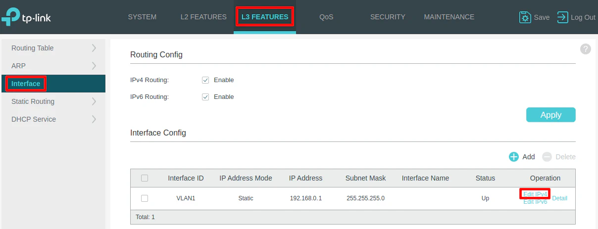
The first thing you should do is change the IP address of the network switch to a static IP address that resides in your management network. In my example, I will set it to 192.168.1.2 so the switch will be included on the LAN network since the router is using 192.168.1.1/24 for the LAN interface. This step is important because you want to make sure all your network infrastructure is accessible within your management network.
Click on the “L3 Features” tab at the top of the page, and then “Interface” on the left side menu. You should see the default IP address. Click on “Edit IPv4” to edit the IPv4 address.
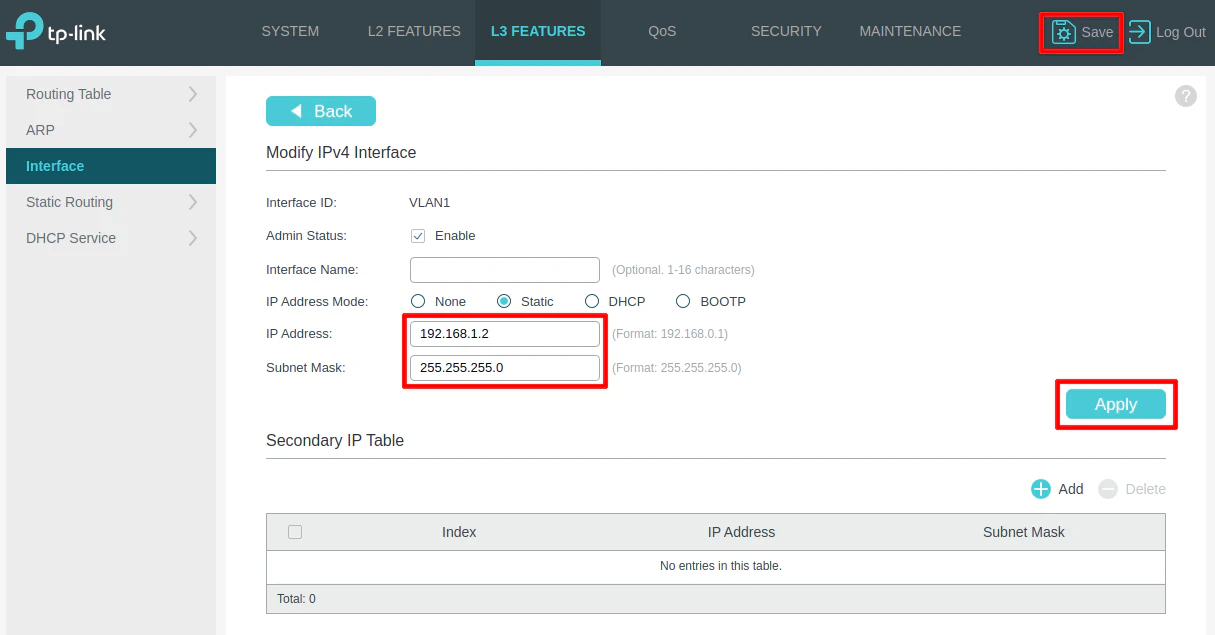
Enter 192.168.1.2 and click “Apply”. You will likely lose connectivity immediately and will have to start using the http://192.168.1.2 web address. There may be the possibility you will need to change your IP address on your PC/laptop to be in the same subnet if you cannot connect to the new IP address on the switch (I cannot easily test this because I do not have an extra switch laying around that I am able to reset without taking down parts of my network).
Be sure to log back in and click on the “Save” button in the upper right hand corner to make sure the changes are persistent once you know you are able to connect to the new IP address. If you do not click “Save” on TP-Link switches, the changes will be lost when you reboot the switch.
Disable DHCP
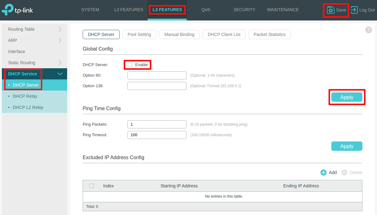
You should check to make sure DHCP is enabled or not. Most likely, you already know based on whether or not your PC obtained an IP address automatically or not.
On the “L3 Features” page, click on the “DHCP Service > DHCP Server” side menu. Then make sure the “Enable” checkbox for the “DHCP Server” is unchecked. Click “Apply” and “Save” to persist the changes.
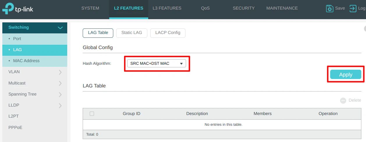
LAG Configuration
On the “L2 Features” page for the “LAG” configuration on the “LAG Table” section, you may select a different hashing algorithm. I like to choose an algorithm that includes both the source and destination as part of the hash so that traffic can be distributed more evenly.
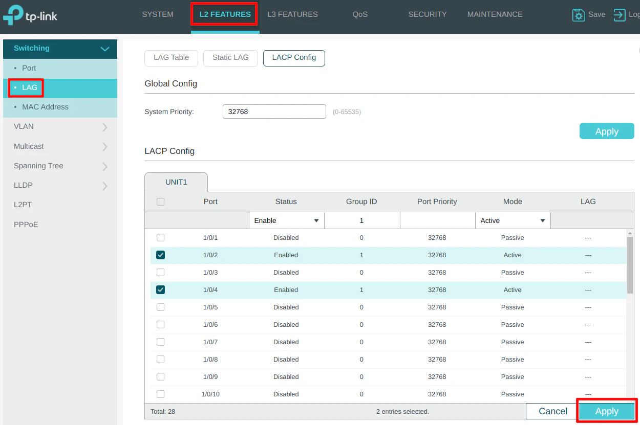
The “LACP Config” section is where the LAG configuration resides. For my example, port 2 and 4 will be a LAG that is connected to OPNsense. Check both ports, choose “Enable” for the “Status”, “Group ID” of 1, leave the port priority at the default value, and choose “Active” for the “Mode”. Click the “Apply” button when you are finished.
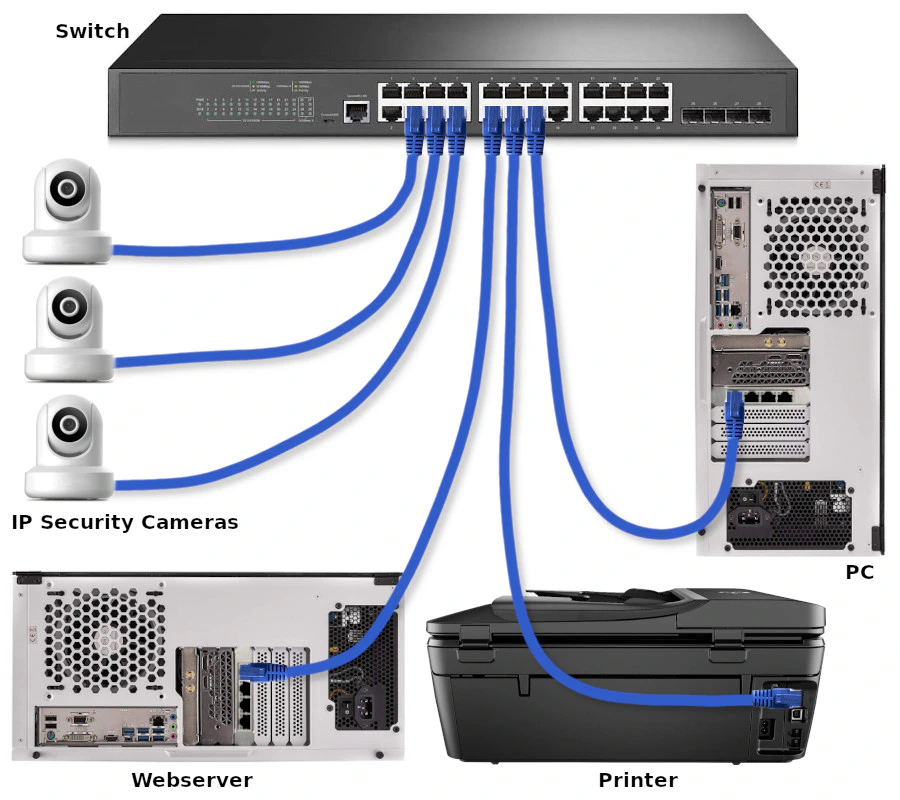
Physical Diagram of Connected Devices
Before proceeding with the VLAN configuration, refer to the following physical diagram for devices/clients connected to the network (see also the physical network infrastructure diagram). It will be beneficial to see which Ethernet ports the devices are plugged into when configuring the switch.
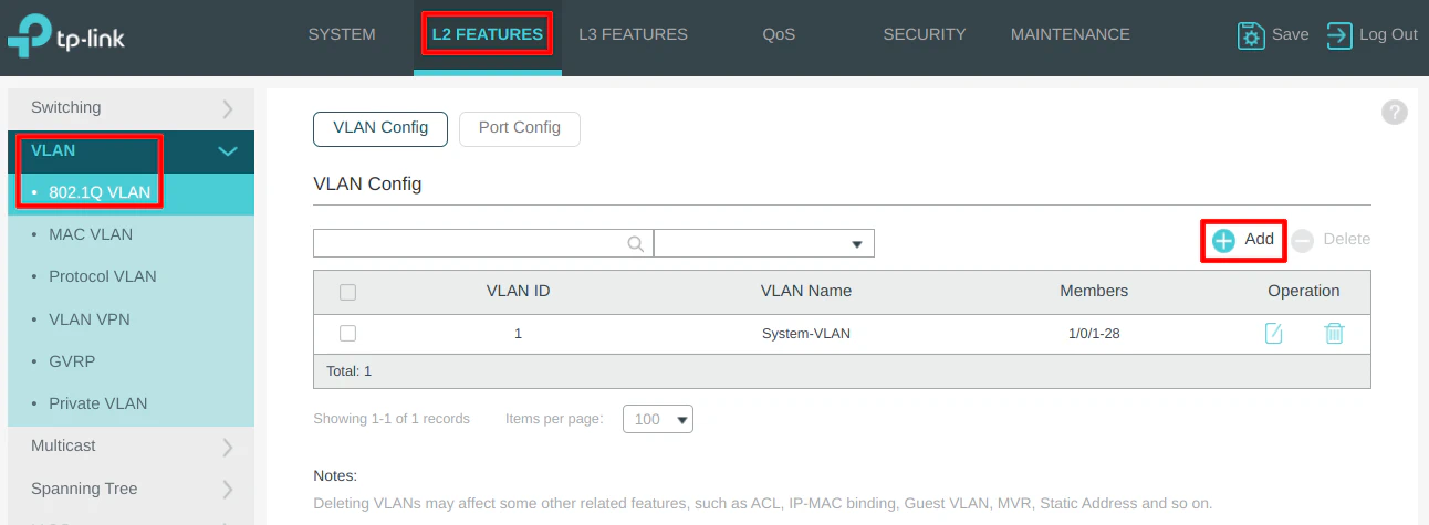
VLAN Configuration
Go to the “L2 Features” page and click on the “VLAN > 802.1Q VLAN” left side menu to see the list of VLANs. By default, every port is assigned VLAN1 which is designated for untagged ports. The managed switch will behave like a basic unmanaged switch by default.
Click the “Add” button to create new VLANs. When the “VLAN Config” dialog box opens, you will see two main sections for “Untagged Ports” and “Tagged Ports”. This may be confusing if you are new to VLANs.
The “Untagged Ports” section is where you select the ports you wish to add to a particular VLAN for all of your wired devices. You can only have an “untagged port” assigned to one VLAN.
The “Tagged Ports” section is only used for ports that are connected to VLAN-aware devices such as routers, switches, wireless access points, and even servers (such as virtualization servers). “Tagged ports” can be assigned multiple VLANs unlike “untagged ports” so that multiple VLANs can pass through one port. Think of tagged ports as an aggregation of multiple VLANs. You will often see the term “trunk port” used to refer to the tagged ports.
VLAN 10 (DMZ)
Enter the “VLAN ID” of 10 for the DMZ network, which is the same value used for OPNsense for the DMZ. They must match. The “VLAN Name” should be “DMZ” so the description matches with the OPNsense VLAN configuration so there is less confusion when maintaining your network configuration.
The DMZ network contains the web server so select port 9 in the “Untagged Ports” section since that is where it is connected in the example network.
You will need to set port 2 and 4 as the “Tagged Ports”. It is more important to have LAG1 set as a tagged port as shown in the next step than setting the individual ports as tagged. I like to tag the individual ports “just in case” (you decide to remove the LAG in the future, for instance), but it is likely not necessary as long as you have the LAG configured.
Note that for the DMZ, you do not need to tag the wireless access point port on port 1 unless you plan to have wireless devices in your DMZ (and you configure the DMZ VLAN on your access points).
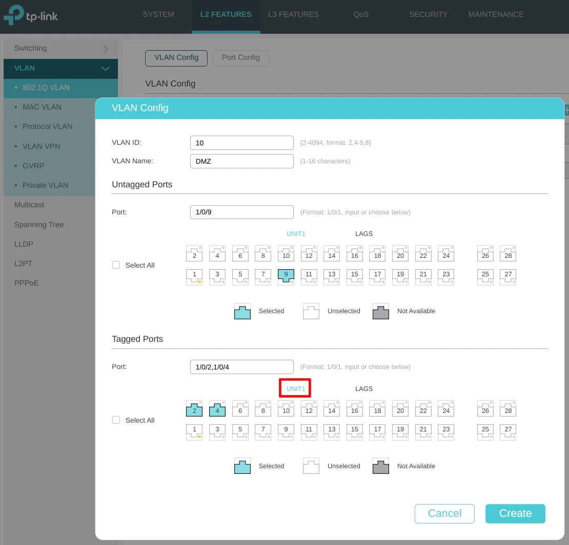
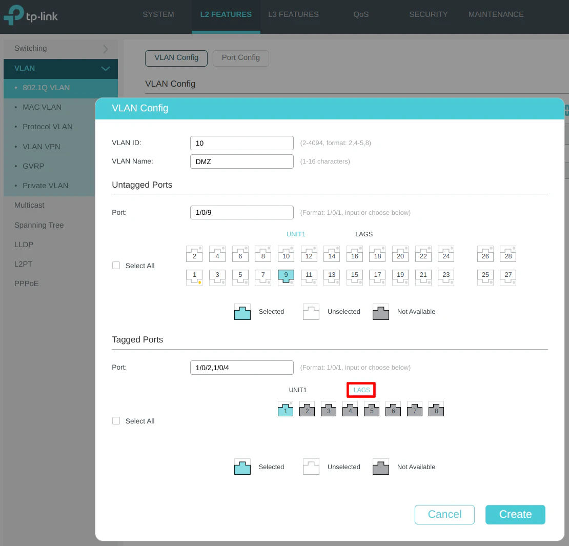
Click on the “LAGS” section on the “Tagged Ports” so that you can select LAG1. This step is important to ensure your VLAN traffic is allowed on the LAG interface.
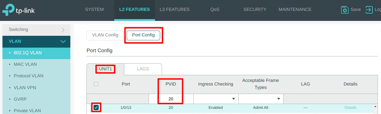
On the “Port Config” section, select port 9 and set the PVID to 10 as the VLAN ID.

VLAN 20 (USER)
Enter the “VLAN ID” of 20 for the USER network, and the “VLAN Name” of “USER”. A PC is connected to the USER network on port 13 so it is selected in the “Untagged Ports” section. Select ports 1, 2, and 4 as the tagged ports include the ports connected to OPNsense as well as the wireless access point.

Include tagging the LAG1 interface to allow the USER network on the LAG.

On the “Port Config” section, select port 13 and set the PVID to 20 as the VLAN ID.
VLAN 30 (IOT)
Enter the “VLAN ID” of 30 for the IOT network, and the “VLAN Name” of “IOT”. A printer is connected to the IOT network on port 11 so it is selected in the “Untagged Ports” section. Select ports 1, 2, and 4 as the tagged ports include the ports connected to OPNsense as well as the wireless access point.
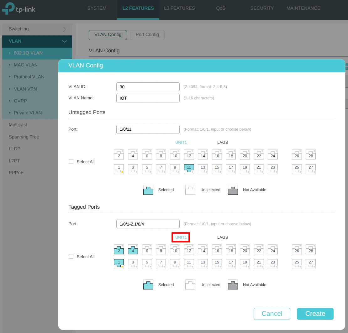
Include tagging the LAG1 interface to allow the IOT network on the LAG.
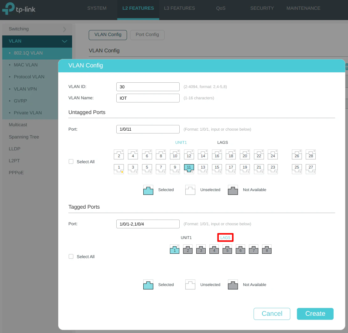
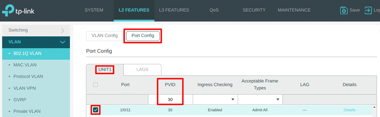
On the “Port Config” section, select port 11 and set the PVID to 30 as the VLAN ID.
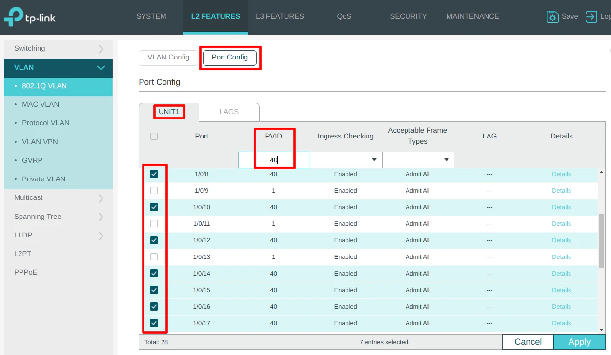
VLAN 40 (GUEST)
For the GUEST network, you should select any unused ports to be on the GUEST network so that devices that are later plugged into the ports do not default to the management LAN network. This is very important if you are worried about users or anything potentially malicious from being connected to your most critical network.
Since I am used the untagged LAN network for management, it means every other port needs assigned to some VLAN to keep devices on the LAN. For this reason, that is why many users (especially for businesses/enterprises) prefer to have a dedicated management VLAN for their network infrastructure.
Even if you have your own dedicated VLAN network for your critical network infrastructure, I still think it is a good idea to default all of the unused ports either to a sinkhole network that has no network connectivity or to a more restrictive network such as the GUEST network. That way if anyone connects to your network, they are already isolated from your network. If you decide you need to change it later for a new device on your network, it is a simple configuration change on your switch.
Enter the “VLAN ID” of 40 for the GUEST network, and the “VLAN Name” of “GUEST”. I do not have any wired devices connected to the GUEST network in my example but all unused ports are selected in the “Untagged Ports” section. Select ports 1, 2, and 4 as the tagged ports include the ports connected to OPNsense as well as the wireless access point.
If you plan to have a dedicated wired device to access all of the management network’s web interfaces, be sure to leave one port available to connect another LAN device. Otherwise, you will not have access to the management interfaces unless you created the appropriate firewall rules (as mentioned in the firewall rules section above).
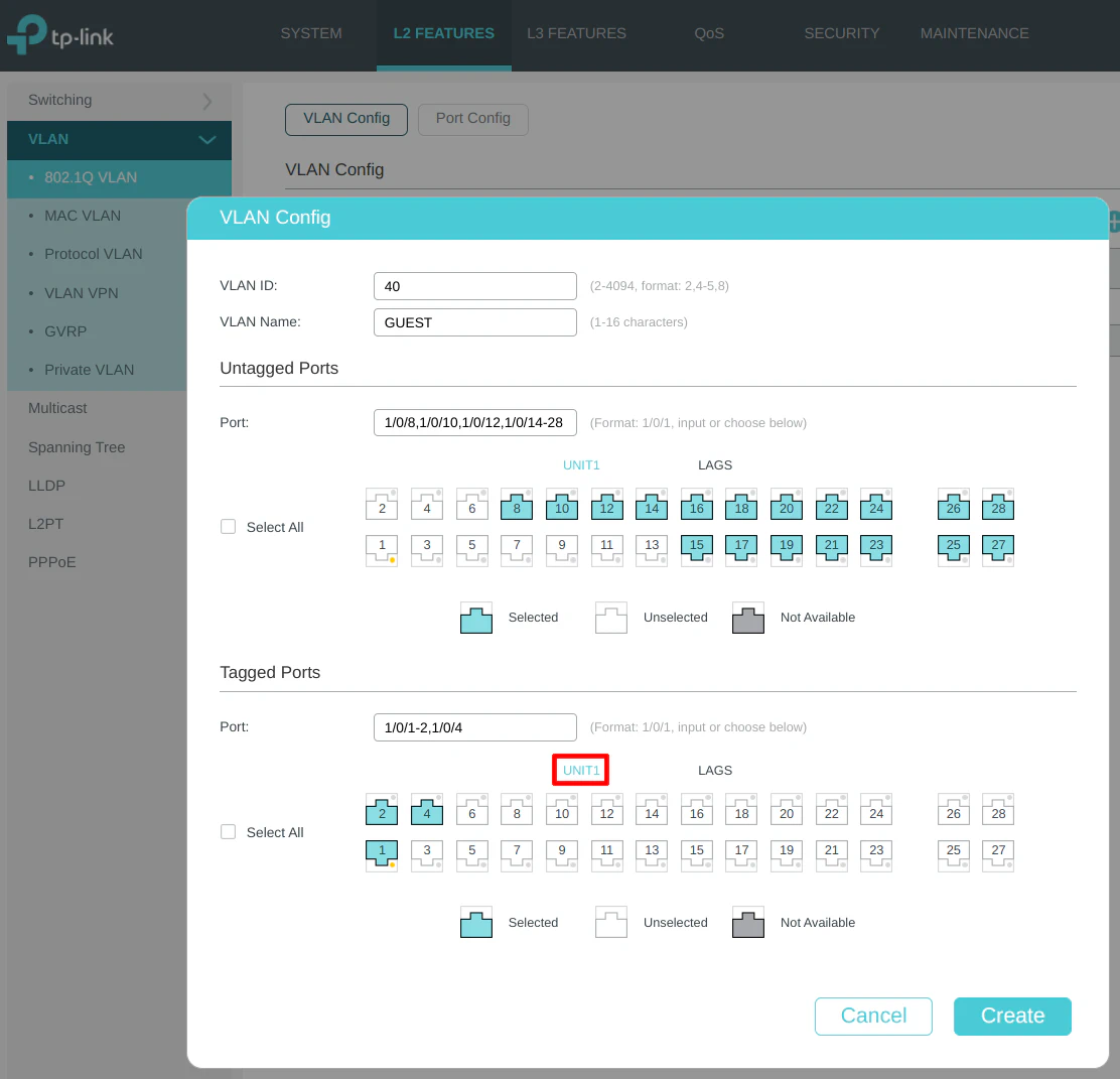
Include tagging the LAG1 interface to allow the GUEST network on the LAG.
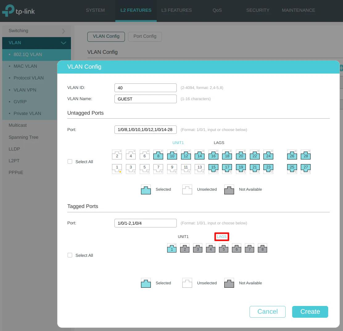
On the “Port Config” section, select the same unused ports as earlier for the GUEST network and set the PVID to 40 as the VLAN ID.
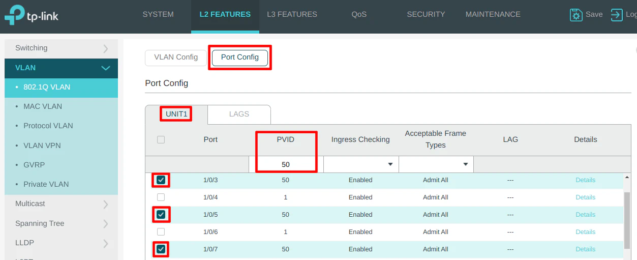
VLAN 50 (IPCAM)
Enter the “VLAN ID” of 50 for the IPCAM network, and the “VLAN Name” of “IPCAM”. IP security cameras are connected to the IPCAM network on ports 3, 5, and 7 so it is selected in the “Untagged Ports” section. Select ports 1, 2, and 4 as the tagged ports include the ports connected to OPNsense as well as the wireless access point.
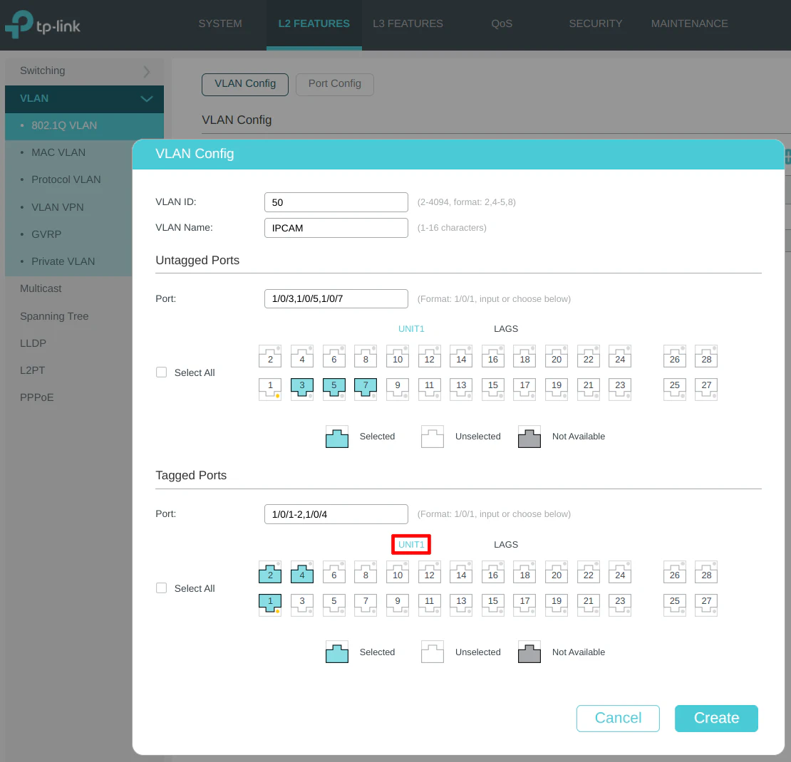
Include tagging the LAG1 interface to allow the IPCAM network on the LAG.

On the “Port Config” section, select ports 3, 5, and 7 to set the PVID to 50 as the VLAN ID.
VLAN 1 (LAN)
VLAN 1 is often used by managed switches as the default for all ports. Any port that is set to VLAN 1 is considered to be untagged and not belonging to any other VLAN (some switches may allow you to change this default behavior).
I saved this configuration until last because some switches may not let you remove ports from VLAN 1 until they are assigned to other VLANs since all ports must be assigned to a VLAN even if it is the default VLAN 1. The ports that are assigned to other VLANs may already be removed from VLAN 1, but I noticed with the newer TP-Link switches, the ports may still show as being assigned to untagged VLAN 1 even when assigned to another VLAN. Most likely the switch is ignoring VLAN 1 when it is assigned to other ports, but I like to fix that so that it easy to see which ports are assigned to other VLANs.
Select port 6, which is connected to the untagged LAN interface of OPNsense, and port 1, which is connected to the UniFi wireless access point. The UniFi AP needs to have the untagged VLAN 1 assigned so that the wireless AP can be managed from the LAN using the UniFi Controller software, which will reside on the LAN as well.
Please be sure to remove VLAN 1 from ports 2 and 4 because only tagged traffic will be on those ports used for the LAG (remember, to keep the untagged and tagged VLAN traffic more separated in OPNsense to reduce the likelihood of accidentally creating rules that could allow access between untagged and tagged networks, which could be a real security concern).
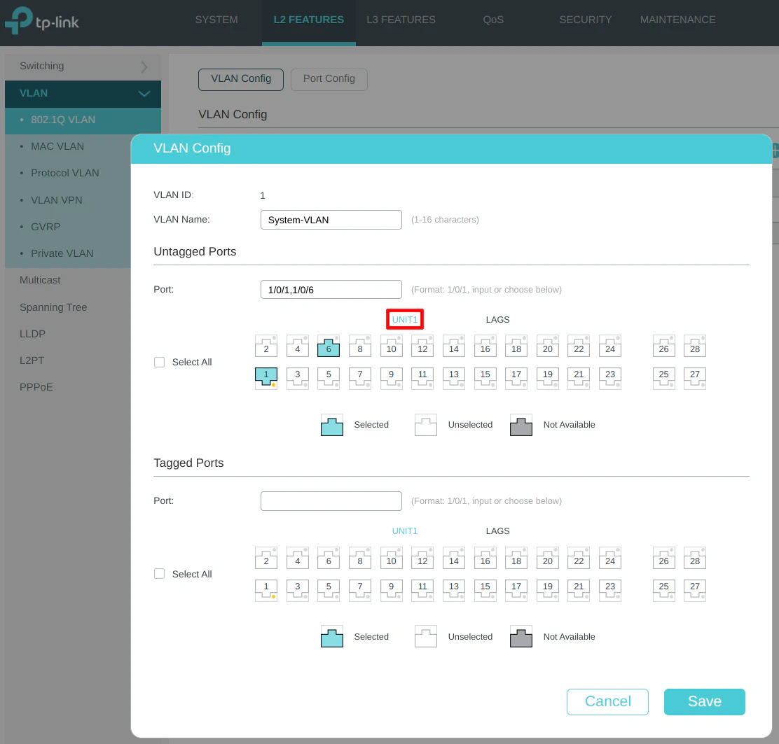
One thing that you should change on the “LAGS” area of the “Untagged Ports” section is to deselect the LAG1 as shown in the screenshot below. The reason is that the LAG should only carry tagged traffic so the tagged and untagged traffic can be separated on the OPNsense interfaces.
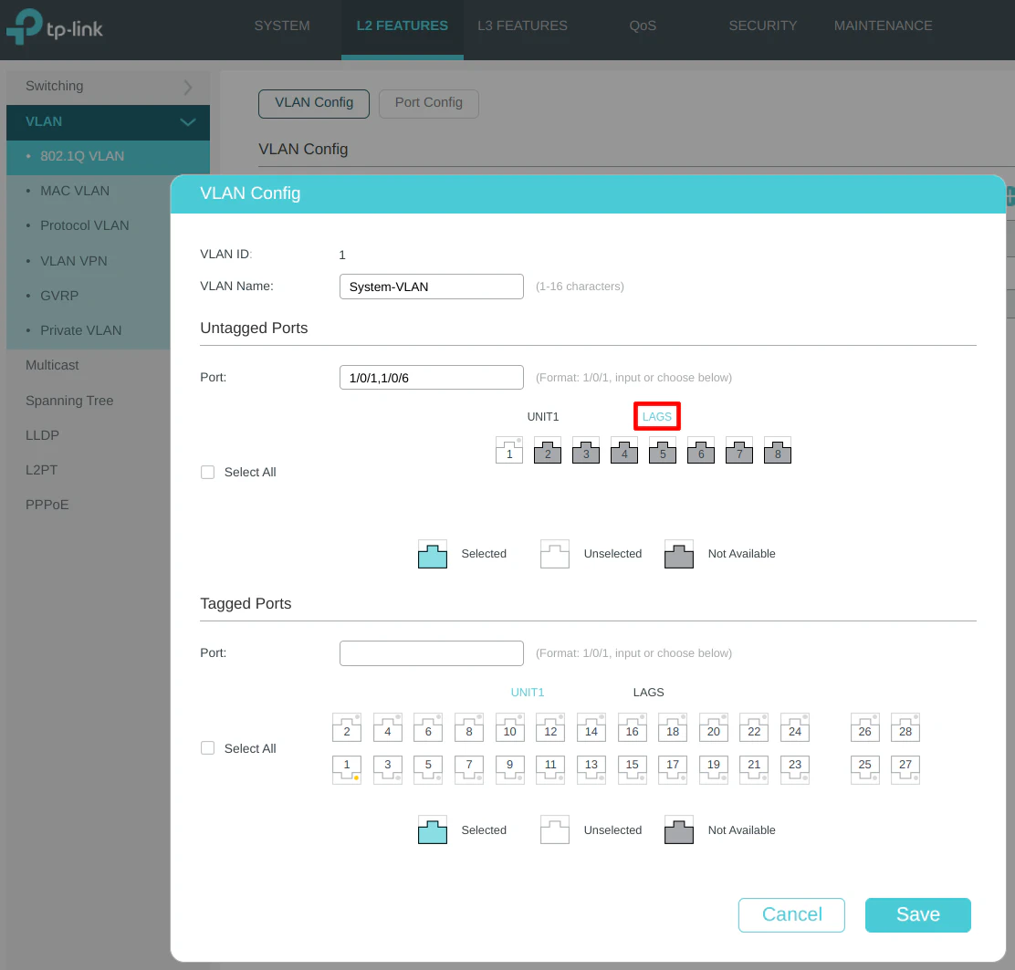
To further ensure only tagged traffic is allowed on the LAG, go to the “Port Config” section, select ports 2 and 4, and set the “Acceptable Frame Types” to “Tagged Only”.
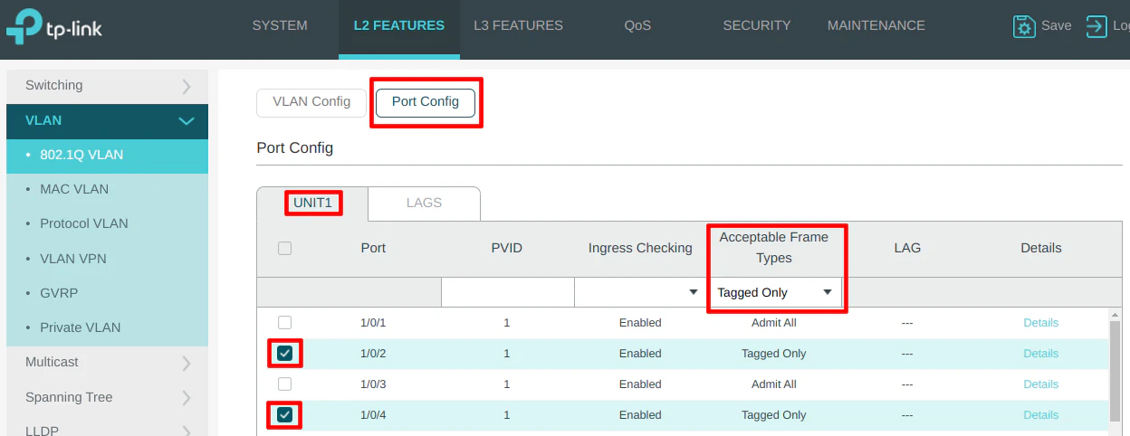
You can do the same thing for the LAG itself by clicking on the “LAGS” tab.
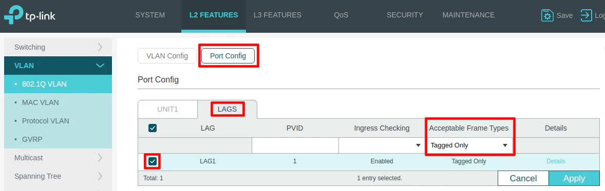
Connect switch to OPNsense and the AP to the Switch
After the switch has been configured, it is time to plug it into OPNsense to see if the LAG and VLAN configuration was successful! Plug the LAN interface of OPNsense into port 6 on the switch and the two interfaces of the LAG on OPNsense into ports 2 and 4 on the switch.
You can tell if the LAG is configured properly by viewing the “LAG Table” on the “LAG” page under “L2 Features”. If you see both port 2 and port 4 as “Members” of the LAG, you know it is functioning properly since it has detected both ports in the LAG configuration. Both ends of the LAG must be configured in order for the LAG to show all of the connected members.
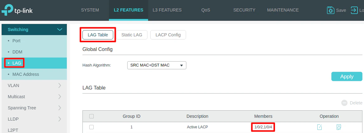
Also plug the UniFi AP into port 1 before proceeding with the configuration in the next section.
Note
As everything is currently configured, you will need to make sure you have either a dedicated device such as something simple like a Raspberry Pi plugged into your LAN so you can access your OPNsense or network switch’s interface. To do that you need to configure one of your switch’s ports to be untagged (VLAN 1) so the device will be on the same network as your network infrastructure.
Alternatively, you could create a firewall rule on the USER interface to allow your PC/laptop access to the web interfaces. However, that opens one hole into the management network. If you do not have any spare devices or you do not want to have to temporarily plug your PC/laptop into the LAN, a firewall rule would be the most convenient option.
Configure Wireless Access Points
Last but not least, the wireless access point needs to be configured. When using a firewall appliance such as the Protectli VP2410, I recommend using external wireless access points rather than using a USB or built-in wireless module. WiFi performance will be much greater and more reliable when using dedicated wireless access point(s) – in particular, APs which have a wired backhaul connection.
A wired backhaul means the wireless AP has an Ethernet cable that is plugged either directly into your router or into a switch that is plugged into your router. Many wireless APs can be powered via PoE (Power over Ethernet) in which case you will need to plug it into a PoE network switch or a PoE injector.
Not all wireless access points support creating VLANs but APs such as UniFi support this feature which means you can add your wireless devices to the same VLANs as your wired devices. I often see others put their WiFi on a separate subnet/VLAN, but that is not necessary (unless you really want your wireless devices completely isolated from your wired devices). For me personally, having my wireless devices on some of the same networks as my wired devices is very convenient.
Because OPNsense and the network switch have been configured for VLANs, all that remains is the VLAN configuration of the AP. There are other parameters you may tweak as well to improve wireless performance, but I am going to focus on the VLAN configuration to get the devices connected. I will leave WiFi performance tuning as an exercise for the reader (perhaps a future topic idea).
I am going to assume the UniFi Controller is already installed and is running on the LAN. By default, the UniFi Controller should be able to find the AP which is plugged into port 1 since port 1 has been configured to allow untagged VLAN 1 traffic as well as VLANs 20, 30, 40, and 50. It not easy for me to demonstrate these steps without having an unused or new AP that I can provision using the UniFi Controller software.
Since the UniFi APs only allow for 4 VLANs on each AP (1 VLAN per SSID), I will demonstrate setting up 4 VLANs.
Tip
Keep in mind that if your wireless spectrum is crowded by having several close neighbors with WiFi, you may wish to limit the number of VLANs because the UniFi APs use separate radios for each VLAN. I have read that performance on UniFi APs can start to diminish when using more than 3 SSIDs but that could depend on how crowded the spectrum is and how many devices are connected to your WiFi network(s).
Create New VLAN Networks
The first thing you need to do is create the VLAN networks. Go to the “Settings” page by clicking the gear button at the bottom of the left side menu and then click on the “Networks” section. By default you will see a “Default” network with the 192.168.1.1 address range. You can leave this default network. Click on “Create New Network” to create a VLAN.
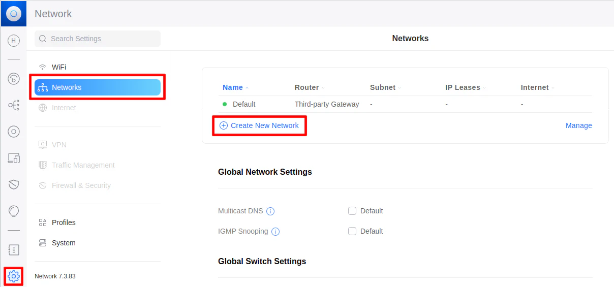
Enter the “Network Name” of “USER (20)” and the “VLAN ID” of 20, which is the same VLAN ID used for the OPNsense/switch VLAN configuration.
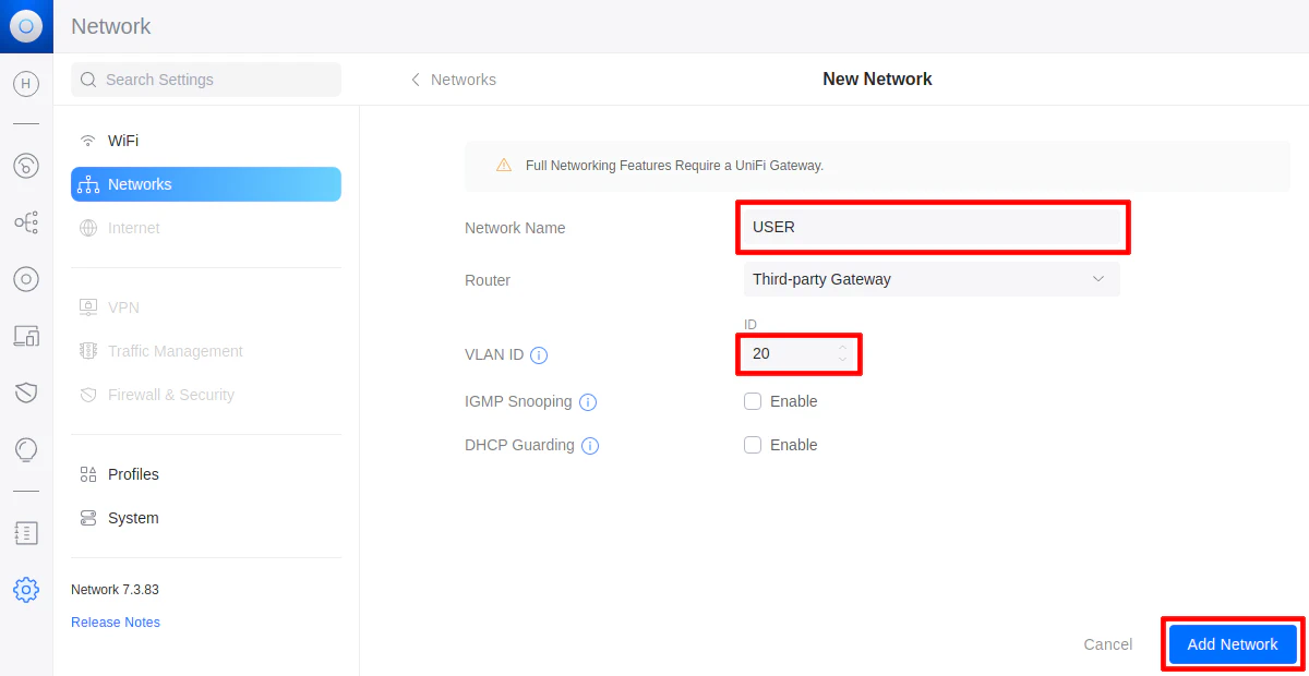
Repeat this step with the other VLANs using the following values:
| Network Name | VLAN ID |
|---|---|
| IOT (30) | 30 |
| GUEST (40) | 40 |
| IPCAM (50) | 50 |
Create New WiFi Networks
Once the networks are added, you can create new WiFi SSIDs – 1 SSID for each VLAN. Click on the “WiFi” section above the “Networks” section. Then you can click on “Create New WiFi”.
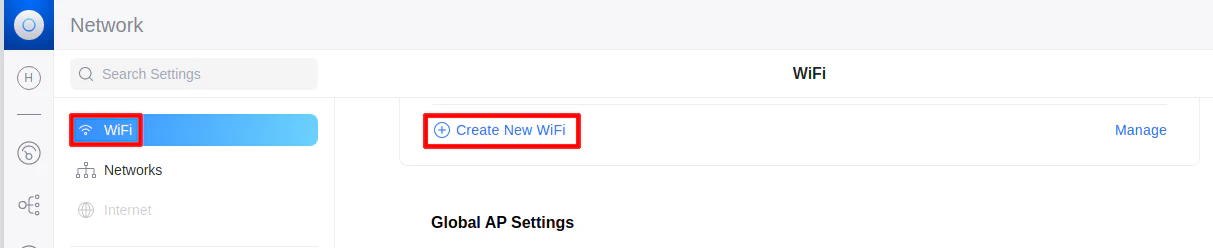
Enter the “Name” of your WiFi network. This network will be visible to anyone with range of your network so I recommend using a more descriptive name than the name of your VLANs. What I like to do is use a common base name and then append the VLAN to SSID so I can tell the networks apart from each other.
Next add the “Password” and select the “Network” that you just created (such as “USER (20)”, etc).
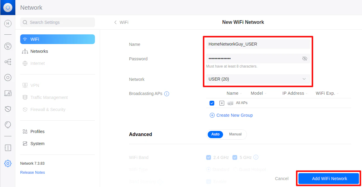
Repeat this process for the other 3 WiFi networks. All of your AP(s) should be provisioned with the new SSIDs and you will be able to connect to them with your wireless devices.
Next Steps
At this point you should have a fully functioning home network with several VLANs to isolate groups of devices on your home network for improved security.
You may want to explore other areas where you can add more features or add more layers of security. I have written another guide for several security related features that you may reference.
I hope this guide helps demonstrate the steps involved with setting up the network infrastructure for a more advanced home network. My goal was to keep the topic constrained as much as possible while also providing a comprehensive example to help you get started with your home network.
If you found this guide to be too complex to begin your journey, please check out my beginner’s guide on creating a full network, which has a greatly simplified network architecture from which you can build upon later as your knowledge and experience grows.